Soldermask opening always is a very important thing for various PCB, esp. for rigid FR4 PCB. In previous article, we already discussed why soldermask opening & tented was not the same like original gerber file.
If you really want soldermask opening for hole (Via) less than 0.60mm, you should added special notice when placing order.
At the same time, there’s another method you can use: To increase the soldermask opening diameter, that means add an “Annular Ringâ€. Normally you will need to increase 0.10mm (4mil) on each side, so that there’ll be a 0.1mm “Annular Ring†around the hole/Via, that Annual ring will stop soldermask into the hole/via of PCB.
Because in a lot of design, if there’s Via/Hole, there’ll no opening in its soldermask file, maybe engineer think the drill will remove the soldermask and then there’ll no soldermask on these Via/hole of board. As mentioned before, if Via/Hole in Printed circuit board was less than 0.6mm, or around 0.65mm then it’ll be a problem.
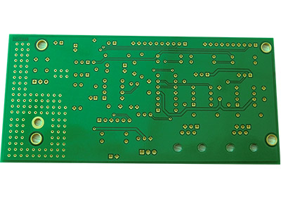
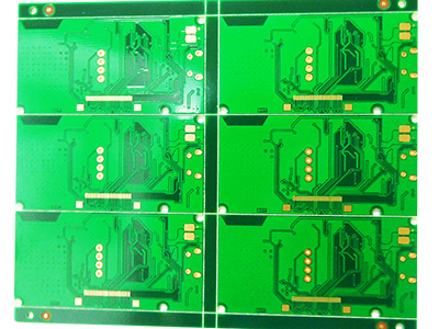
See from bellowing pictures of PCB board:
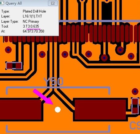
0.635mm Drill hole (Via)
(0.635mm Drill hole (Via)
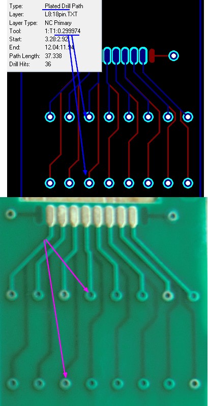
This is the original PCB Gerber file, the diameter of drill hole was 0.635mm and there’s no soldermask opening on GTS (top soldermask) Gerber file. (Purple color was GTS, Yellow: GTL (top layer); Blue: Drill (PTH) file), and no Annular Ring.
So final circuit boards will be like belowing:
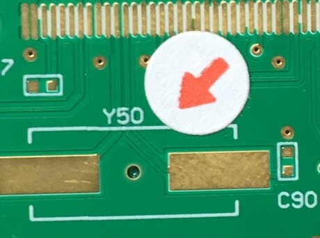
0.635mm Via covered/tented by soldermask
So you need to add at least 0.10mm (4mil) soldermask opening on each side of hole, so that there’ll be a 0.1mm Annular Ring, like bellowing:
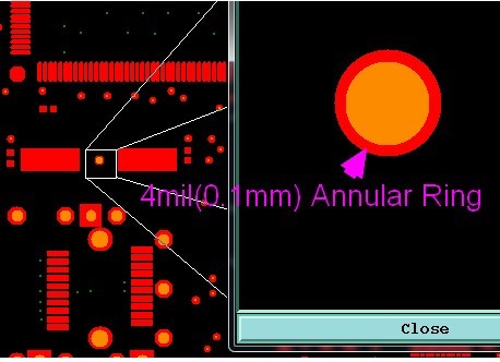
Add 4mil Annular Ring on PCB Via
Then that hole will become like bellowing:
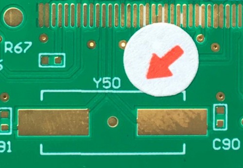
Hole/Via without soldermask (soldermask opened)
We believe there’re a lot of other handling method about that soldermask opening, please leave your comments, or contact us to discuss more about that, and believe you will be happy to receive with the PCB with correct soldermask opening!
Tags: FR4 PCB, PCB soldermask


