
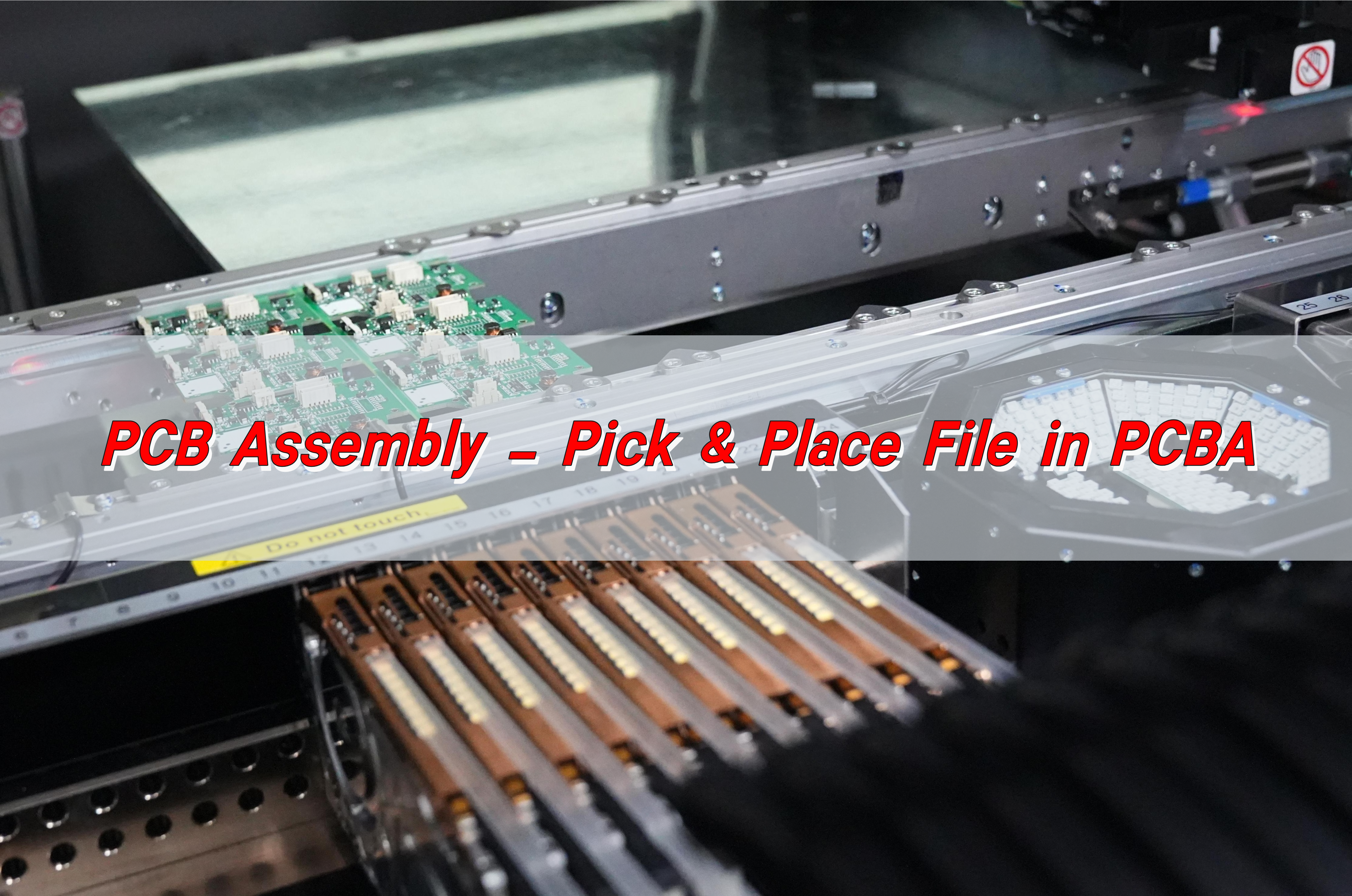
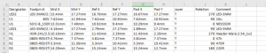
Pick and Place File is a key file in PCBA, which is used to guide automated equipment (such as placement machines) to accurately pick up and place components to specified locations on the PCB. This file usually contains information such as the reference number of each component, the X and Y coordinates on the PCB, the rotation angle (direction), and the mounting layer (top or bottom layer).
What is the Pick and Place File for PCB?
A Pick and Place (PnP) file, sometimes called the XY file, is a data file used in PCB assembly. It contains crucial information about the placement of surface-mount components (SMDs) on the board. This file is used by pick-and-place machines to accurately position components.
Without this file, manufacturers would need to manually place each component, which would be time-consuming and prone to errors. A well-prepared pick and place file ensures efficient, precise, and automated assembly, reducing costs and improving overall production quality.
What is the Centroid File in PCB?
The centroid file is another term for the pick and place file. It contains the X and Y coordinates for each component’s center, along with its rotation angle and reference designator. These details allow assembly machines to pick the components correctly and place them in the exact locations on the PCB.
This file is crucial for automated PCB assembly because it minimizes placement errors and ensures that all parts align correctly with the circuit design.
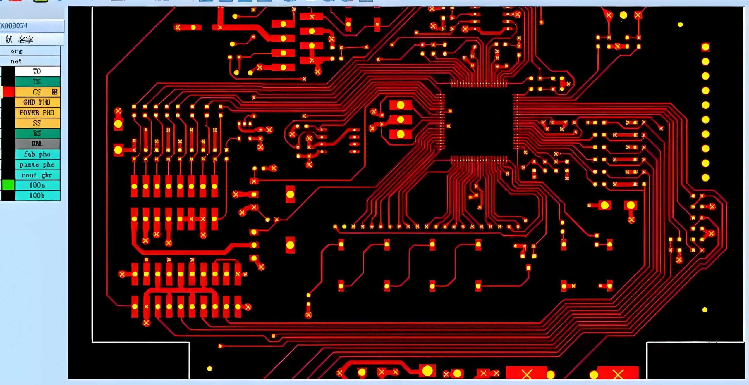
What are Gerber Files in PCB?
Gerber files are a different type of file used in PCB manufacturing. While a pick and place file provides component placement data, Gerber files define the PCB’s physical layout. These files describe the copper layers, solder mask, silkscreen, and drill holes.
Both files are essential for PCB production:
Gerber files ensure the PCB is fabricated correctly.
Pick and place files guide the assembly process by positioning the components.
Together, these files allow for smooth PCB manufacturing and assembly.
What Information is Included in a Pick and Place File?
A pick and place file contains several key details:
- Reference Designators – Identifies each component (e.g., R1, C2, U3).
- X and Y Coordinates – Specifies the precise location of each part.
- Rotation Angle – Determines how the component should be oriented.
- Package Type – Ensures compatibility with the pick and place machine.
This information ensures that each component is placed in the exact spot, aligned properly, and ready for soldering.
How to Make a Pick and Place File?
Creating a pick and place file depends on the PCB design software being used. Most modern design tools can automatically generate this file.
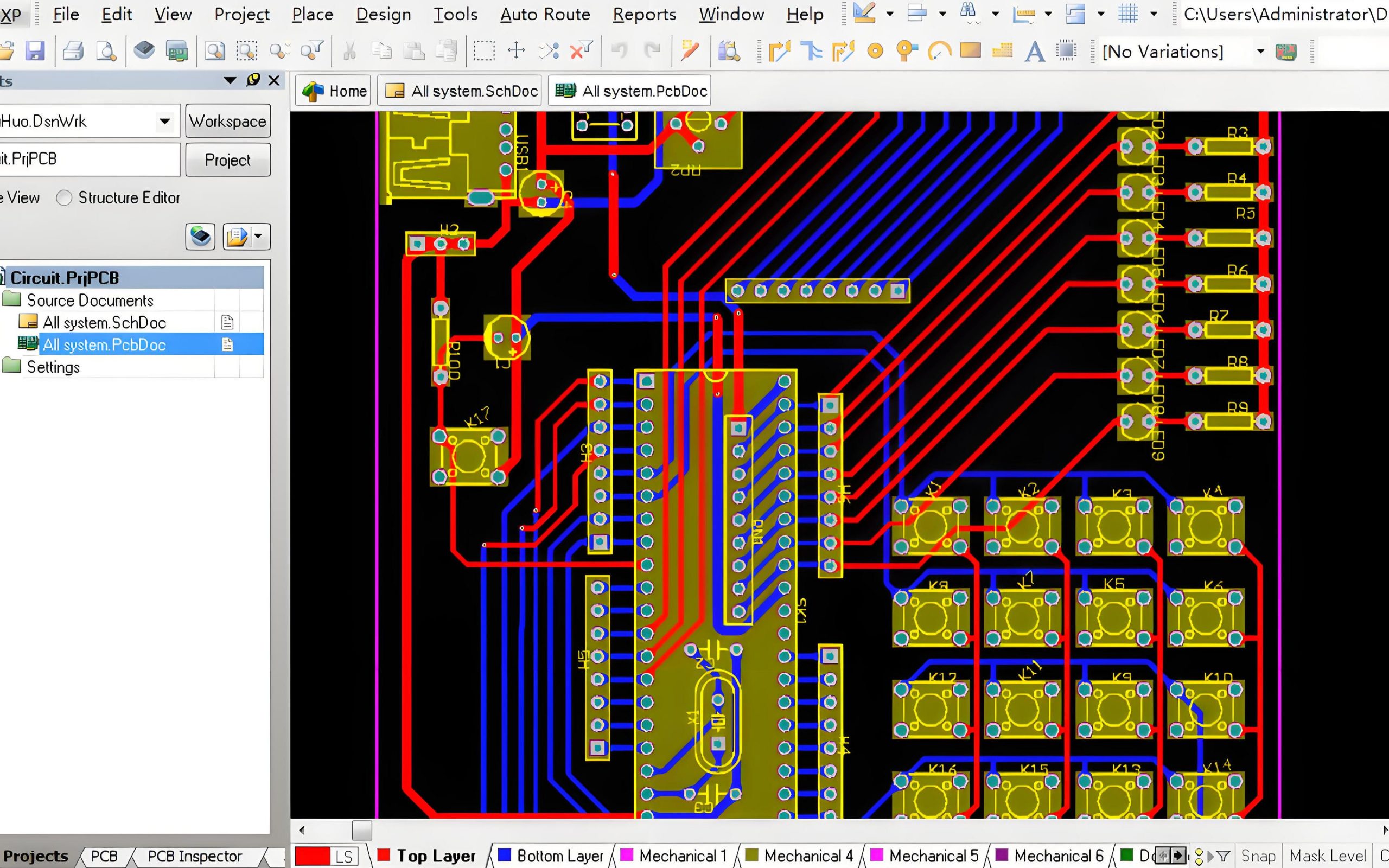
In Altium Designer
- Open your PCB layout file.
- Click File > Assembly Outputs > Generate Pick and Place.
- Select the file format required by the assembly house.
- Save and export the file.
In KiCad
- Open your PCB design in KiCad.
- Go to File > Fabrication Outputs > Footprint Position File.
- Choose the output format and export the file.
In Eagle
- Open your PCB project.
- Go to Tools > Run ULP > Mount.smd.ulp.
- Save the output file.
Most PCB manufacturers provide guidelines on how they want the pick and place file formatted. Always confirm their requirements before sending the file.
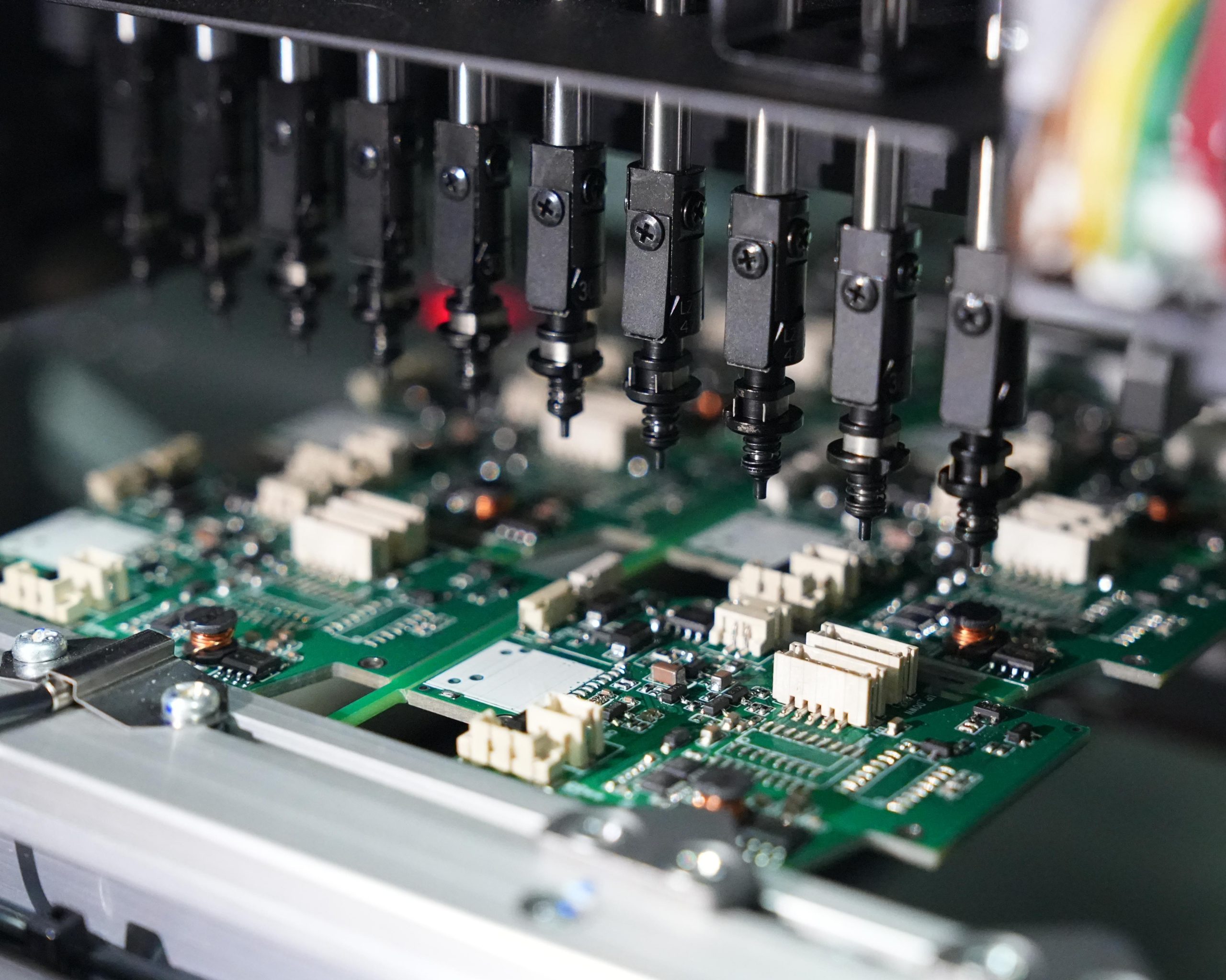
What is the Pick and Place Process?
The pick and place process is an essential part of Surface Mount Technology (SMT) assembly. It involves the automated placement of components onto a PCB. The steps include:
- Component Preparation – Components are loaded into feeders or trays.
- Machine Calibration – The pick and place machine is set up according to the PCB design.
- File Processing – The pick and place file is loaded into the system.
- Component Pickup – The machine’s nozzles pick up components using vacuum suction.
- Component Placement – The machine positions each part according to the file’s coordinates.
- Inspection – The placement is verified before reflow soldering.
This automated process ensures high accuracy and fast assembly speeds.
How Fast is a Pick and Place Machine?
Pick and place machines operate at varying speeds depending on their model and capabilities. The speed is measured in Components Per Hour (CPH).
Entry-level machines can place 5,000 – 10,000 components per hour.
Mid-range machines can handle 30,000 – 50,000 CPH.
High-end machines exceed 100,000 CPH, making them ideal for mass production.
The faster the machine, the more efficient the assembly process, reducing production time and costs.
Why is a Pick and Place File Essential?
Using a pick and place file provides several benefits:
- Improved accuracy – Ensures precise component placement.
- Faster production – Speeds up PCB assembly.
- Reduced errors – Minimizes misalignment and incorrect component placement.
- Lower costs – Reduces labor costs by automating placement.
Without this file, the assembly process would be slower, less efficient, and more prone to errors.
Conclusion:
A pick and place file is a critical component of PCB assembly. It provides essential data for automated machines, ensuring precision, efficiency, and high-quality production.
Advanced pick and place machines make modern PCB assembly faster, more accurate, and cost-effective. If you need high-quality PCB assembly services, contact sales@bestpcbs.com for expert solutions.
You may also like


Tags: Pick and place file Altium, Pick and place file format, Pick and place machine