
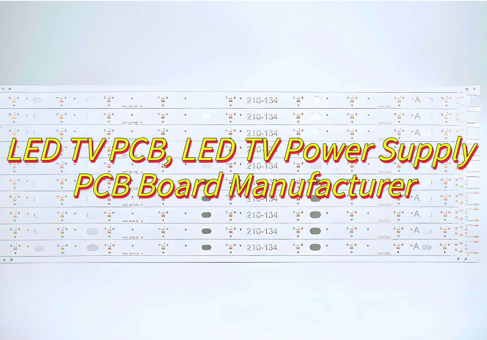
Why choose LED TV PCB solutions? This analysis covers PCB specs, pricing by screen size, safety testing, efficiency optimization, cost controls, and quality checks for reliable TV power boards.
Best Technology leads as a LED TV PCB board manufacturer by delivering UL/IEC/CE-certified boards with 95%+ energy efficiency and advanced thermal solutions. Our PCBs undergo rigorous AOI/X-ray testing, ensuring 100,000+ hour lifespans and compliance with global voltage standards. Customizable designs adapt to diverse screen sizes (32” to 85”) and enable cost-effective 4K/smart TV upgrades, while optimized production minimizes costs for high volume OEM partnerships. Welcome to contact us if you have any request for LED TV PCB: sales@bestpcbs.com
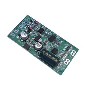
What Is LED TV PCB?
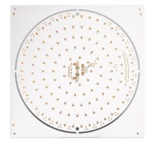
A LED TV PCB (Printed Circuit Board) serves as the central nervous system of a modern LED television, connecting and controlling its electronic components. It houses critical circuits for power management, signal processing, and backlight control. For instance, power boards in these PCBs often use advanced architectures like LLC resonance to efficiently convert AC power into multiple DC outputs, while backlight driver circuits regulate voltage and current for consistent screen illumination. Manufacturers increasingly adopt materials like aluminum-clad PCBs for heat dissipation or explore glass substrates for high-resolution Mini LED displays. These boards also integrate communication interfaces, audio processors, and smart TV modules, enabling features like 4K streaming and voice control. As TV designs evolve toward slimmer profiles and higher brightness, PCB layouts prioritize compact component arrangements and thermal management solutions to balance performance with durability.
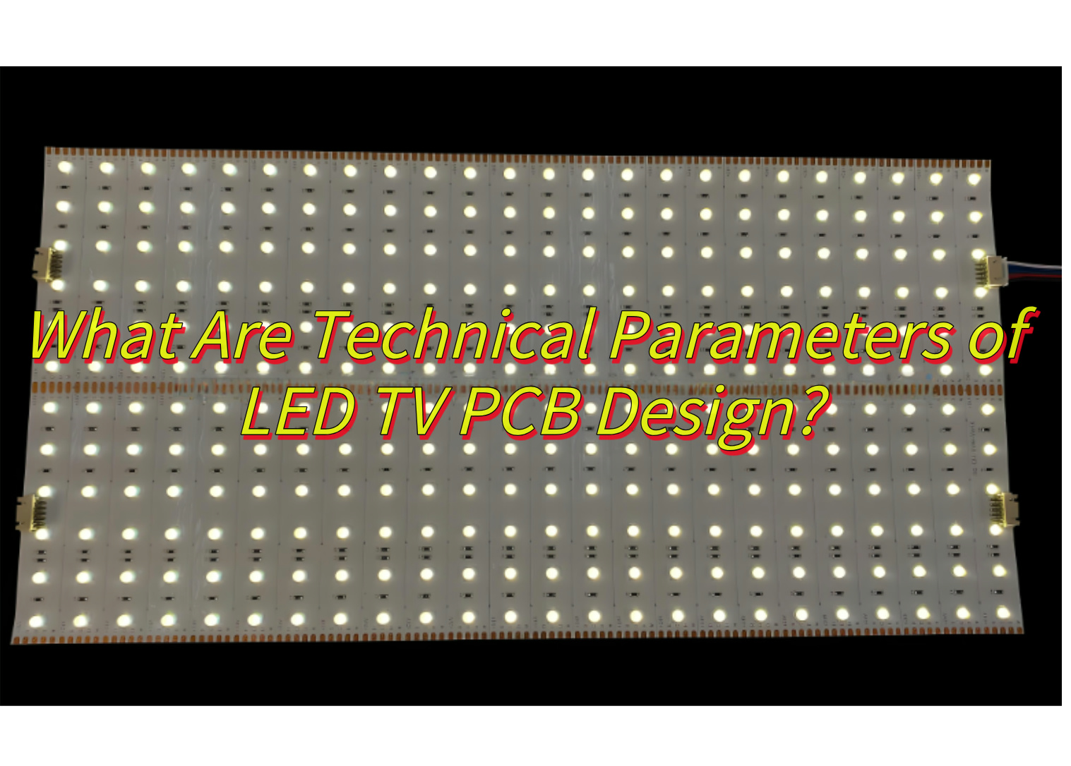
What Are Technical Parameters of LED TV PCB Design?
Essential Technical Parameters for LED TV PCB Design:
Power Management Specifications
- Input Voltage Range: Supports 100-240V AC input for global compatibility.
- Output Configuration: Delivers multiple DC outputs (3.3V/12V/24V) with total power exceeding 190W in advanced models.
- Circuit Architecture: Utilizes hybrid topologies like LLC resonance + PFC to achieve 90%+ energy efficiency.
Backlight Driver Requirements
- Current Regulation: Maintains stable output currents (0.5-2A) for LED arrays to prevent flicker or uneven brightness.
- Dimming Compatibility: Integrates PWM (Pulse Width Modulation) and DC dimming modes for dynamic contrast adjustments.
Physical Design Constraints
- Layer Stack-up: High-end models employ 6-8 layers PCBs with embedded copper cores for heat dissipation.
- Thickness Optimization: Slim designs target ≤2mm thickness using ultra-thin dielectric materials.
Thermal Performance Metrics
- Heat Dissipation: Aluminum-clad substrates or ceramic-filled laminates reduce thermal resistance to ≤1.2°C/W.
- Component Layout: Strategically positions high-power components (e.g., MOSFETs) near cooling vents or heatsinks.
Signal Integrity Features
- Impedance Control: Maintains ±10% tolerance for high-speed HDMI/USB interfaces to minimize signal loss.
- EMI Shielding: Incorporates grounded copper pours and ferrite beads to meet FCC/CE emission standards.
Smart Function Integration
- Wireless Connectivity: Allocates dedicated zones for Wi-Fi 6/Bluetooth 5.3 modules with antenna isolation design.
- Processor Support: Provides BGA (Ball Grid Array) mounting pads for SoCs.
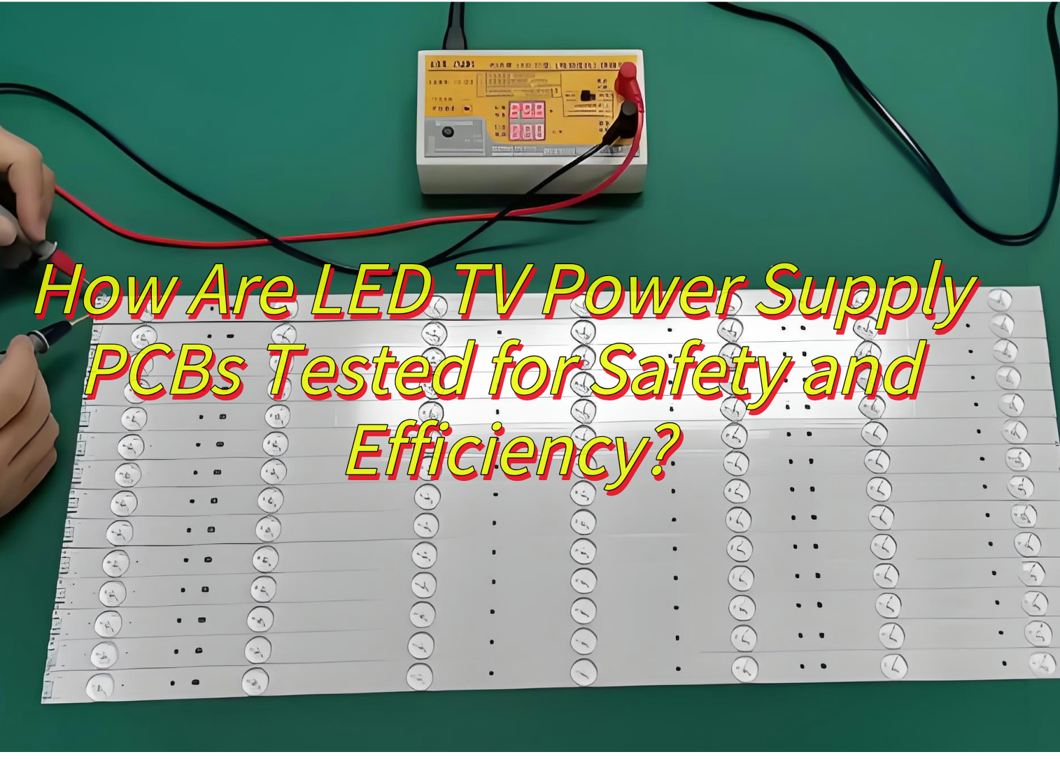
How Are LED TV Power Supply PCBs Tested for Safety and Efficiency?
LED TV Power Supply PCB Testing Procedures:
1.Electrical Safety Verification
- High-voltage insulation checks: Conducted at 3kV AC for 60 seconds to ensure no arcing or breakdowns, meeting IEC 60950 standards.
- Overload protection testing: Simulates 150% rated load for 30 minutes to verify automatic shutdown mechanisms.
- Leakage current measurement: Uses specialized meters to confirm currents stay below 0.25mA during normal operation.
2.Thermal Stress Analysis
- Infrared thermography: Identifies hot spots exceeding 85°C during continuous 72-hour operation tests.
- Heat dissipation validation: Monitors temperature drops using aluminum-clad PCBs under maximum brightness settings.
3.Efficiency Evaluation
- Input/output power measurement: Precision power analyzers calculate efficiency ratings (≥90% for Energy Star compliance).
- Standby power consumption: Verifies power draw below 0.5W when the TV is in sleep mode.
4.Component Reliability Checks
- Capacitor aging tests: Subjects electrolytic capacitors to 105°C environments for 1,000+ hours to assess lifespan.
- Solder joint inspections: Automated optical systems detect cracks or voids in high-current connection points.
5. Certification Compliance
- EMI/EMC testing: Validates electromagnetic interference levels within FCC Part 15 limits using anechoic chambers.
- Safety certifications: Third-party labs perform UL/CE certification tests covering fire resistance and material flammability.
How to Improve the Efficiency of LED TV Power Supply PCB?
Effective Methods to Enhance LED TV Power Supply PCB Efficiency:
Circuit Architecture Optimization
- Compact current paths: Keep primary power loops under 5cm to minimize parasitic inductance losses.
- Advanced topologies: Implement PFC (Power Factor Correction) combined with QR (Quasi-Resonant) designs to achieve over 93% conversion efficiency.
High Performance Power Components
- Wide-bandgap semiconductors: Replace traditional MOSFETs with Gallium Nitride or Silicon Carbide devices, reducing switching losses by 40%.
- Low-drop diodes: Use Schottky diodes with forward voltage ≤0.3V to minimize rectification heat generation.
Transformer Design Improvements
- Advanced core materials: Adopt nanocrystalline cores instead of ferrite to cut iron and copper losses by 20%.
- Winding techniques: Apply interleaved winding to reduce leakage inductance, limiting ringing effects to ±5%.
Thermal Management Upgrades
- Enhanced PCB substrates: Switch to aluminum-clad or ceramic-filled laminates with thermal resistance below 0.8°C/W.
- Direct heat-path design: Mount high-heat components like MOSFETs directly onto heatsinks, reducing temperature gaps by 15-20°C.
Capacitor Selection Strategies
- Low-ESR capacitors: Use 105°C-rated electrolytic capacitors to handle 30% higher ripple currents.
- MLCC parallel arrays: Deploy X7R-type multilayer ceramic capacitors at output stages to suppress high-frequency noise.
PCB Layout Refinements
- Multi-layer construction: Implement 6+ layer boards with internal copper shielding for EMI reduction and heat distribution.
- Ground separation: Physically isolate digital and power grounds to prevent interference-induced losses.
EMI Reduction Techniques
- Dual-stage filtering: Install two common-mode chokes at AC inputs to attenuate conducted emissions below 30dBμV.
- Localized shielding: Apply copper foil shielding near high-frequency switching nodes to cut radiated emissions by 40-50%
Power IC Enhancements
- Stable auxiliary supply: Integrate linear regulators to maintain control chip voltage at 15V±5%, lowering thermal stress.
- Smart standby modes: Use power management ICs with ≤0.3W sleep-mode consumption to meet Energy Star V3.0.
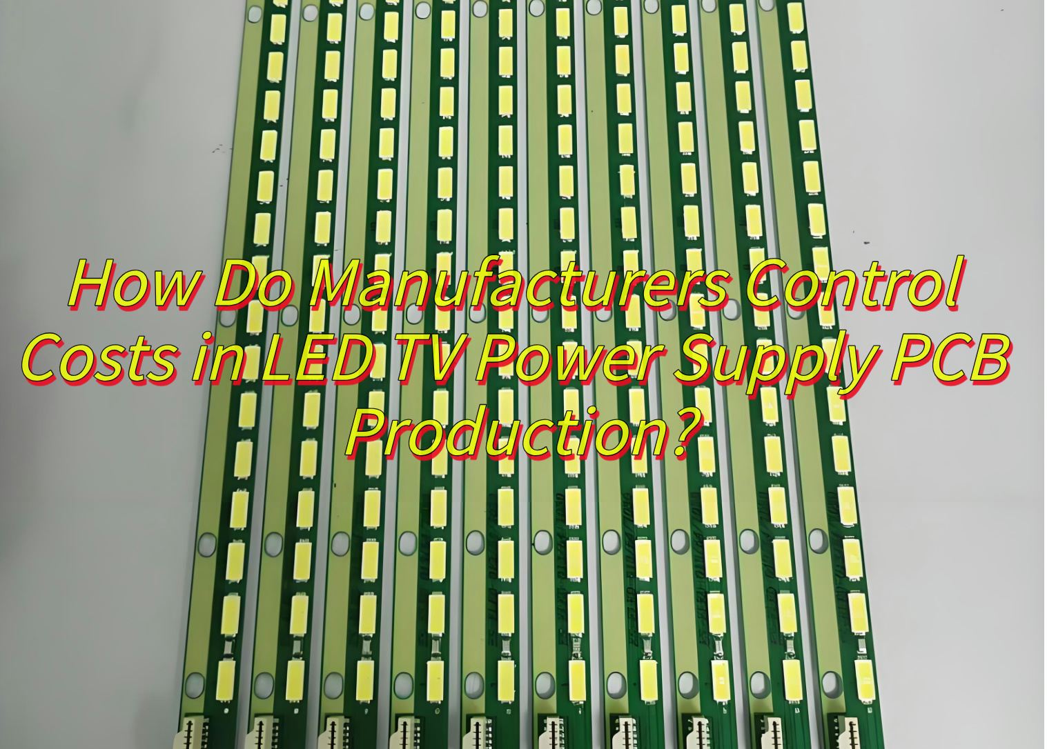
How Do Manufacturers Control Costs in LED TV Power Supply PCB Production?
Here are strategies about how LED TV power supply PCB manufacturer control production costs:
Material Procurement Optimization
- Bulk purchasing: Source FR-4 substrates and copper-clad laminates in 10k+ unit batches to secure 12-18% volume discounts.
- Supplier partnerships: Negotiate multi-year contracts with local component vendors (within 150km radius) to reduce logistics expenses by 20-25%.
Design Standardization
- Layer reduction: Convert 6-layer designs to optimized 4-layer layouts where feasible.
- Unified hole patterns: Standardize via diameters at 0.3mm±0.05mm across models, minimizing laser drill bit replacement costs.
Automated Assembly Implementation
- High-speed SMT lines: Deploy 80,000 CPH (components per hour) pick-and-place machines with ≤50ppm defect rates.
- 3D AOI systems: Integrate automated optical inspection to reduce manual QC labor by 70% while maintaining 99.98% fault detection accuracy.
Production Waste Minimization
- Panel nesting algorithms: Achieve 96%+ material utilization from raw PCB sheets through optimized cutting patterns.
- Lead-free reflow: Adopt SAC305 soldering alloys to keep rework rates below 0.8% across batches.
Energy-Conscious Manufacturing
- Regenerative burn-in: Recover 35-40% of test energy in thermal cycling processes using capacitor banks.
- LED curing systems: Replace 5kW UV ovens with 800W LED arrays for solder mask hardening, cutting energy use by 84%.
Smart Testing Protocols
- Statistical sampling: Test 8% of units per batch using Six Sigma methods instead of 100% inspection, reducing test time by 65%.
- Parallel aging: Run 120+ PCBs simultaneously in multi-zone climate chambers, halving validation durations.
What Quality Checks Ensure Reliable LED TV PCB Board Performance?
Manufacturers implement multi-stage quality checks to ensure LED TV PCB board meet performance standards. Here’s a structured overview:
Incoming Material Inspection (IMI)
- Component Verification: Test resistors, capacitors, and ICs for tolerance compliance.
- Visual Inspection: Check PCBs for scratches, delamination, or solder mask defects.
Pre-Assembly Checks
- Stencil Printing Validation: Verify solder paste volume and alignment for accurate component placement.
- Pick-and-Place Accuracy: Calibrate SMT machines to ensure components are placed within ±0.05mm.
Post-Assembly Inspections
- Automated Optical Inspection (AOI): Detect solder bridges, missing components, or polarity errors.
- X-Ray Inspection: Verify BGA and QFN solder joints for hidden defects.
Functional Testing
- Power-On Tests: Measure voltage outputs, ripple, and standby power consumption.
- Signal Integrity Checks: Use oscilloscopes to validate HDMI, USB, and other digital signals.
Environmental Stress Tests
- Thermal Cycling: Expose PCBs to -40°C to 85°C cycles to identify solder joint fatigue.
- Humidity-Heat Testing: Simulate tropical conditions (85% RH, 85°C) to check for corrosion.
Regulatory Compliance
- Safety Certifications: Ensure PCBs meet UL, CE, or FCC standards for electromagnetic interference (EMI) and insulation.
- RoHS/REACH Compliance: Verify absence of hazardous materials in components and solder.
Final Quality Audit (FQA)
- Statistical Sampling: Pull units from production batches for retesting to catch sporadic defects.
- Traceability Records: Maintain component lot numbers and test data for future reference.
What Is the Price of A LED TV PCB Board for Different Screen Sizes?
The cost of LED TV PCBs varies by screen size, features, and brand. Here’s a general price breakdown:
32-Inch HD TVs
- Basic PCBs: $25–$50 (supports 720p resolution, limited HDMI ports).
- Premium Models: $40–$60 (includes smart TV firmware compatibility).
43-Inch 4K TVs
- Standard Boards: $60–$100 (4K@30Hz support, basic HDR).
- High-End Variants: $100–$150 (60Hz refresh rate, Android OS integration).
55-Inch+ Ultra HD TVs
- Mid-Range PCBs: $120–$200 (HDMI 2.1, MEMC motion smoothing).
- Flagship Models: $250–$350+ (OLED/QLED support, gaming features).
Factors Affecting Price
- Resolution/Refresh Rate: 4K@120Hz boards cost 30%–50% more.
- Smart Features: Wi-Fi, Bluetooth, and voice control add $20–$80.
- Brand vs. Generic: OEM replacements are 20%–40% pricier than aftermarket boards.
Can A 32-Inch Universal LED TV PCB Be Upgraded to Support 4K or Smart TV Features?
Whether a 32-inch universal LED TV PCB can support 4K or smart TV upgrades depends on several factors. Here’s a structured analysis:
Hardware Limitations
- Chipset Compatibility: The existing PCB’s processor must support 4K decoding (e.g., H.265/HEVC) and smart OS integration.
- Memory Constraints: Insufficient RAM/flash storage may prevent smart features or 4K streaming.
- Panel Interface: The display panel’s LVDS/eDP connector must match the PCB’s output capabilities for 4K resolution.
Software and Firmware
- Firmware Updates: Check if the manufacturer provides updates to enable 4K or smart functions via USB or OTA.
- Operating System: A compatible OS (e.g., Android TV, Linux) is required for app support and streaming services.
Upgrade Costs and Availability
- PCB Replacement Cost: A new PCB with 4K/smart features may cost 30%–50% of the TV’s original price.
- Market Availability: Universal PCBs for 32-inch TVs may lack advanced features due to lower demand.
Practical Steps for Upgrading
- Research Compatibility: Verify the TV model’s PCB part number and feature support with the supplier.
- Purchase and Installation: Source a compatible PCB, ensuring it matches the TV’s chassis and connector layout.
- Professional Assistance: Hire a technician for safe disassembly and reprogramming, if required.
Potential Risks
- Warranty Void: Unauthorized PCB swaps may void the TV’s warranty.
- Performance Mismatch: A 32-inch screen may not fully benefit from 4K due to pixel density limitations.
In conclusion, while technically possible if hardware allows, upgrading a 32-inch TV’s PCB for 4K/smart features is often cost-prohibitive. For most users, purchasing a new TV with native 4K/smart capabilities is more practical.
You may also like


Tags: led tv pcb, led tv pcb manufacturer, led tv power supply pcb board manufacturer