What is a surface mount LED PCB and why is it pivotal in modern electronics? This guide explores its benefits, assembly processes, manufacturer selection, quality control, and weatherproofing for optimized performance and durability.
Best Technology excels in surface mount LED PCB circuit board assembly, combining precision engineering with rapid production to meet diverse industrial demands. Our SMT assembly lines feature high-speed pick-and-place machines (30,000+ CPH) and closed-loop reflow ovens, ensuring ±30μm placement accuracy for complex layouts like 5050 RGB LEDs and 0.5mm pitch components. Advanced AOI (Automated Optical Inspection) and X-ray systems detect solder voids or misalignments, achieving >99.8% first-pass yield. Leveraging vertical integration, we source premium materials (e.g., 2W/m·K aluminum cores, SAC305 solder paste) in-house, eliminating delays. Our optimized supply chain and 24 hours rapid prototyping for urgent orders, backed by flexible capacity for urgent orders. Thermal simulations and rigorous testing (1,000-hour humidity/thermal cycling) guarantee 85°C stable operation for 15W+ LED arrays. Feel free to contact us today: sales@bestpcbs.com.
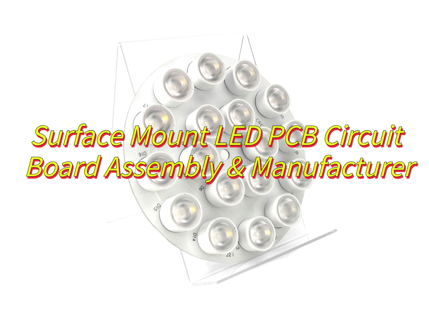
What Is A Surface Mount LED PCB?
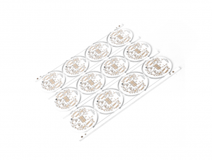
A surface mount LED PCB refers to a printed circuit board specifically designed to integrate surface-mount technology (SMT) for mounting LEDs directly onto its surface, eliminating the need for through-hole components. These PCBs utilize automated assembly processes to place miniature LED chips (e.g., 1206 or 0805 packages) onto solder pads, enabling high-density layouts, improved thermal management (via materials like FR4 or aluminum-core substrates), and compact designs ideal for applications such as backlighting, automotive lighting, or wearable electronics. A specialized variant, surface mount LED that exits through the PCB, features LEDs partially embedded into the board with their emission surfaces protruding through pre-milled openings, combining SMT efficiency with directional light control for indicators or panel-mounted displays. This design ensures mechanical stability, enhanced heat dissipation, and IP-rated durability in demanding environments.
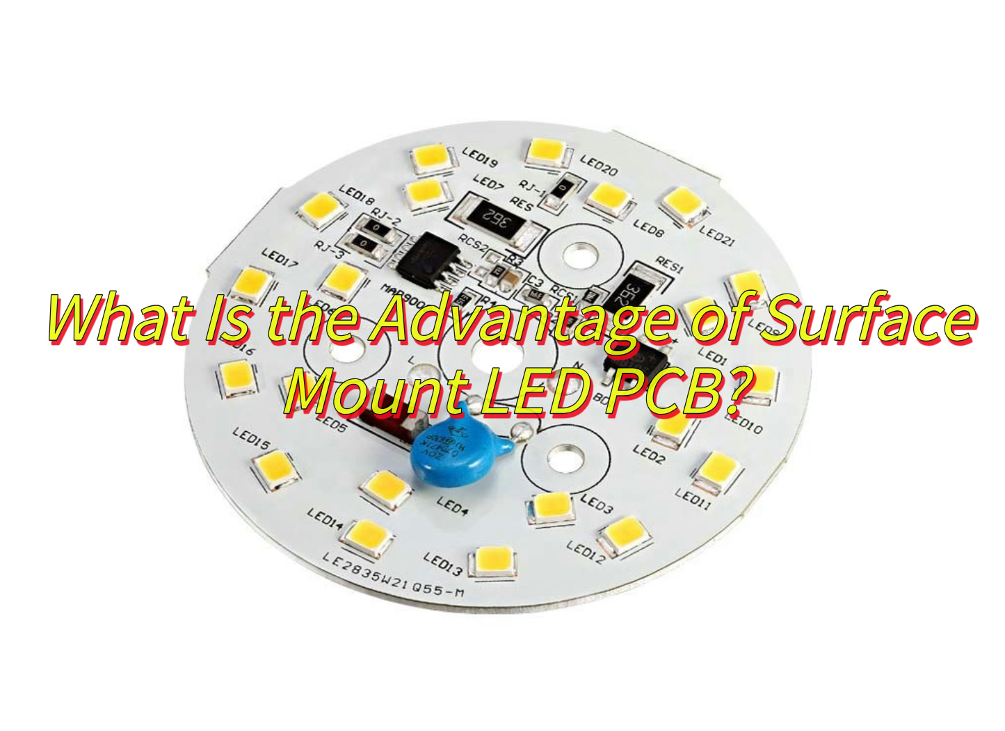
What Is the Advantage of Surface Mount LED PCB?
Surface Mount LED PCB (Printed Circuit Board) technology offers multiple benefits that enhance performance, efficiency, and applicability in modern electronics. Below is a detailed breakdown of its advantages:
Compact Design and High-Density Integration
- Space Efficiency: Surface Mount LED PCBs enable smaller PCB footprints by eliminating the need for through-holes. This allows for denser component placement, critical for miniaturized devices like smartphones, wearables, and automotive interior lighting.
- Lightweight Construction: Reduced material usage and smaller PCB dimensions lower the overall weight of electronic products, improving portability and energy efficiency.
Enhanced Electrical Performance
- Improved Signal Integrity: Shorter signal paths and reduced parasitic inductance/capacitance minimize signal loss and electromagnetic interference (EMI), ensuring stable operation at high frequencies (up to 3GHz).
- Thermal Management: Efficient heat dissipation through PCB layers prolongs LED lifespan, even under prolonged usage in applications like outdoor displays or industrial lighting.
Cost-Effective Manufacturing
- Automated Assembly: Compatibility with SMT (Surface Mount Technology) production lines reduces labor costs and accelerates mass production.
- Material Savings: Smaller PCBs and fewer drilling requirements lower raw material consumption, while advanced surface finishes (e.g., OSP, ENIG) balance cost and durability.
Durability and Environmental Resistance
- Robust Construction: Surface Mount LEDs withstand vibrations and mechanical stress better than through-hole counterparts, making them ideal for automotive, aerospace, and harsh industrial environments.
- Weatherproof Options: Specialized coatings and conformal layers protect PCBs from moisture, dust, and extreme temperatures, enabling outdoor use in LED streetlights or marine applications.
Design Flexibility and Aesthetic Appeal
- Slim Profiles: Ultra-thin PCBs allow for sleek product designs, such as edge-lit TVs or flexible LED strips.
- Uniform Lighting: Advanced SMD (Surface Mount Device) LEDs ensure consistent brightness and color mixing, critical for high-resolution displays and architectural lighting.
Energy Efficiency and Sustainability
- Low Power Consumption: Surface Mount LEDs operate at lower voltages and currents compared to traditional LEDs, reducing energy costs.
- RoHS Compliance: Lead-free manufacturing processes align with global environmental regulations, minimizing ecological impact.
Versatility in Applications
- Consumer Electronics: Backlighting for LCDs, keypads, and appliances.
- Automotive: Interior ambient lighting, dashboard indicators.
- Industrial: Machinery status displays, safety signage.
- Commercial: Digital signage, retail lighting solutions.
Reliability and Longevity
- Reduced Failure Rates: Automated soldering ensures consistent joint quality, minimizing defects.
- Extended Lifespan: High-quality surface finishes and thermal management extend PCB operational life to over 100,000 hours for LEDs.
What Is the Difference Between Surface Mount and Through-Hole LED PCB?
Surface Mount (SMT) and Through-Hole (THT) LED PCBs represent two distinct assembly technologies, each with unique attributes tailored to specific applications. Below is a structured comparison highlighting their differences:
Assembly Process
Surface Mount LED PCB:
- LEDs are mounted directly onto the PCB surface using solder paste and automated pick-and-place machines.
- Reflow soldering melts the solder, creating permanent electrical and mechanical connections.
- Ideal for high-volume production due to speed and precision.
Through-Hole LED PCB:
- LEDs are inserted into pre-drilled holes on the PCB, and leads are soldered manually or via wave soldering on the opposite side.
- Labor-intensive and slower, limiting scalability.
Space Utilization
Surface Mount:
- Enables compact designs by eliminating hole drilling, freeing up space for additional components.
- Supports multi-layer PCBs and high-density layouts.
Through-Hole:
- Requires dedicated holes for each LED, increasing PCB size and limiting component density.
Electrical Performance
Surface Mount:
- Shorter signal paths reduce inductance and resistance, improving high-frequency performance (e.g., in RF applications).
- Better suited for high-speed data transmission and precision circuits.
Through-Hole:
- Longer leads introduce parasitic capacitance, potentially degrading signal integrity at high frequencies.
Thermal and Mechanical Stability
Surface Mount:
- LEDs are prone to thermal stress during soldering but perform well under normal operating conditions.
- Less durable in high-vibration environments compared to through-hole alternatives.
Through-Hole:
- Stronger mechanical bonds due to leads passing through the PCB, offering superior resistance to shock and vibration.
- Better for applications like automotive controls or industrial equipment.
Cost and Scalability
Surface Mount:
- Lower per-unit costs at scale due to automation.
- Initial setup (e.g., stencils, reflow ovens) requires investment but pays off in mass production.
Through-Hole:
- Higher labor costs and slower throughput increase expenses, especially for complex boards.
Repair and Prototyping
Surface Mount:
- Difficult to repair without specialized tools (e.g., hot air rework stations).
- Prototyping may require stencils or skilled technicians.
Through-Hole:
- Easier to replace components manually, favoring prototyping and low-volume runs.
Aesthetic and Design Flexibility
Surface Mount:
- Allows for sleek, low-profile designs (e.g., ultra-thin TV backlighting).
- Uniform light emission due to tight component spacing.
Through-Hole:
- LEDs extend above the PCB, limiting design aesthetics but enabling angled or adjustable lighting.
Typical Applications
Surface Mount:
- Consumer electronics (smartphones, laptops), automotive dashboards, and high-resolution displays.
Through-Hole:
- Industrial controls, prototyping boards, and devices requiring ruggedness over compactness.
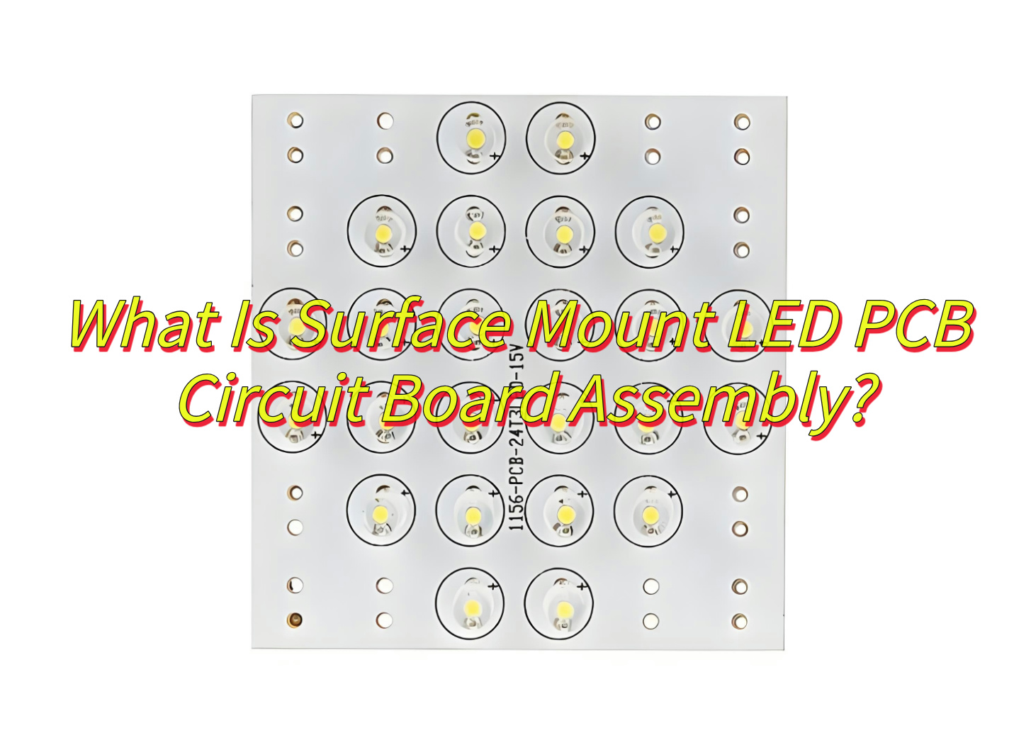
What Is Surface Mount LED PCB Circuit Board Assembly?
A surface mount LED PCB circuit board assembly refers to the process of attaching surface-mount device (SMD) LEDs onto a printed circuit board using automated surface-mount technology (SMT), where components are directly placed and soldered onto predefined solder pads without requiring drilled holes. This method employs solder paste application, precision placement via pick-and-place machines, and reflow soldering to secure miniature LEDs (e.g., 1206 or 0805 packages) onto the PCB surface, enabling high-density layouts and compact designs. Specialized configurations may include surface-mount LEDs that exit through the PCB, where the light-emitting portion protrudes via milled openings for directional applications like indicators or panel displays. The assembly ensures efficient thermal management through conductive substrates like aluminum-core PCBs and supports scalable, high-volume production for applications ranging from consumer electronics to automotive lighting.
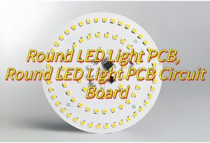
What Steps Are Required For 15 Watt Surface Mount PCB Disc RGB LED Assembly?
Assembling a 15-watt surface mount PCB disc RGB LED involves precision engineering to ensure thermal management, electrical performance, and color accuracy. Below is a structured breakdown of the process:
1. PCB Preparation
- Clean the PCB surface to remove contaminants (e.g., flux residue, dust) using isopropyl alcohol and lint-free wipes.
- Inspect solder pads for oxidation or damage; repair or replace the PCB if issues are detected.
- Apply a thin layer of thermal interface material (TIM) if the LED requires direct contact with a heat sink.
2. Component Placement
- Use a vacuum pick-and-place machine to position the 15W RGB LED disc accurately on the PCB, aligning its pads with the solder paste.
- Ensure polarity alignment (e.g., anode/cathode markers) to prevent electrical failures.
- Place supporting components (e.g., resistors, capacitors, PWM controllers) nearby to minimize trace lengths.
3. Soldering Process
- For mass production: Pass the PCB through a reflow oven with a temperature profile tailored to the solder paste’s specifications (e.g., 245°C peak for lead-free alloys).
- For prototyping: Use a hot air rework station with a nozzle sized to the LED disc to avoid overheating adjacent components.
- Avoid excessive heat exposure to prevent LED degradation or delamination of the PCB substrate.
4. Thermal Management Integration
- Attach the LED disc to a metal-core PCB (MCPCB) or aluminum heat sink using thermal adhesive or screws, ensuring full contact.
- Verify thermal conductivity by measuring the temperature rise during operation (target: below 85°C at maximum load).
5. Electrical Connection and Wiring
- Solder fine-gauge wires (e.g., 24 AWG) to the LED’s anode/cathode pads and RGB channels, using a microscope for precision.
- Insulate connections with heat-shrink tubing or conformal coating to prevent short circuits.
- For RGB control, connect the LED to a microcontroller or driver IC capable of PWM signal modulation.
6. Testing and Calibration
- Perform initial optical testing using an integrating sphere to measure luminous flux, color temperature, and CRI (Color Rendering Index).
- Calibrate the LED’s RGB channels using software to achieve accurate color mixing (e.g., 16.7 million color options).
- Conduct thermal cycling tests (-20°C to 85°C) to validate long-term reliability under temperature fluctuations.
7. Quality Assurance
- Conduct visual inspections for solder joint integrity, component alignment, and signs of overheating.
- Test electrical continuity across all connections using a multimeter.
- Run a 24-hour burn-in test at 100% load to identify early-life failures.
8. Final Assembly and Packaging
- Secure the PCB assembly into its housing (e.g., waterproof enclosure for outdoor applications).
- Label the product with power ratings, safety certifications, and part numbers.

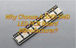
How to Select A Reliable Surface Mount LED PCB Manufacturer?
Choosing a reliable surface mount LED PCB manufacturer requires evaluating technical expertise, quality control, and industry reputation. Below is a structured guide to assist in the selection process:
Certifications and Standards Compliance
- Verify certifications such as ISO 9001 (Quality Management), ISO 14001 (Environmental Management), and UL (Safety Standards).
- Check for compliance with RoHS (Restriction of Hazardous Substances) and REACH regulations if targeting European markets.
Production Capacity and Technology
- Assess equipment modernity (e.g., SMT lines with 6-axis robots, automated optical inspection (AOI) systems).
- Inquire about minimum order quantities (MOQs) and lead times for prototypes versus mass production.
- Confirm capability to handle high-power LEDs (e.g., 15W RGB discs) and specialized PCB materials (e.g., aluminum-backed MCPCBs).
Quality Control Measures
Request details on testing protocols:
- In-Circuit Testing (ICT) for electrical functionality.
- X-ray Inspection for solder joint integrity in hidden layers.
- Thermal Cycling Tests to simulate long-term operational stress.
- Review defect rates (e.g., <0.1% return rate) and warranty policies.
Material Sourcing and Traceability
- Ensure use of high-quality substrates (e.g., FR-4, Rogers 4003C) and LED components from reputable suppliers (e.g., Cree, Osram).
- Confirm lot traceability for raw materials to enable root-cause analysis in case of failures.
Design for Manufacturability (DFM) Support
- Evaluate whether the manufacturer offers DFM feedback to optimize PCB layouts for automated assembly.
- Check for compatibility with common design software (e.g., Altium, Eagle) and file formats (Gerber, ODB++).
Customer References and Case Studies
- Request references from clients in similar industries (e.g., automotive lighting, consumer electronics).
- Review case studies demonstrating expertise in complex projects (e.g., weatherproof LED boards, high-lumen RGB assemblies).
Supply Chain Resilience
- Inquire about contingency plans for material shortages or geopolitical risks.
- Confirm lead time reliability during peak seasons (e.g., holiday orders for LED lighting products).
Ethical and Sustainability Practices
- Audit labor practices (e.g., fair wages, safe working conditions) if corporate social responsibility is a priority.
- Assess recycling programs for scrap PCBs and hazardous waste management.
Pricing and Payment Terms
- Compare quotes across manufacturers, but prioritize value over cost alone.
- Negotiate flexible payment terms (e.g., 30% deposit, 70% upon shipment) for large orders.
Communication and Cultural Fit
- Gauge responsiveness via email/phone during initial inquiries.
- Confirm project managers speak fluent English (or your preferred language) to avoid miscommunication.
How to Control Quality in Surface Mount LED PCB Manufacturing?
Ensuring robust quality in Surface Mount LED PCB manufacturing requires a multi-layered approach combining advanced technology, rigorous testing, and process discipline. Below is a structured guide to achieving consistent reliability:
Incoming Material Inspection
- Substrate Verification: Check PCB laminates (e.g., FR-4, aluminum-backed MCPCB) for dielectric thickness, copper plating uniformity, and impurities using X-ray fluorescence (XRF) analyzers.
- Component Authentication: Validate LEDs, resistors, and capacitors against datasheets using automated optical inspection (AOI) and electrical parameter testing (e.g., forward voltage, luminous flux).
Design for Manufacturability (DFM) Review
- Conduct cross-functional reviews to identify potential assembly risks (e.g., insufficient solder pad spacing, inadequate thermal vias).
- Use design software tools (e.g., Valor NPI) to simulate solder paste deposition and component placement accuracy.
Solder Paste Inspection (SPI)
- Measure solder paste volume, height, and alignment pre-reflow using 3D SPI machines to prevent defects like solder bridges or insufficient joints.
- Adjust stencil thickness (e.g., 0.1mm for fine-pitch LEDs) based on real-time data.
Automated Optical Inspection (AOI)
- Post-reflow AOI systems detect component misalignment, tombstoning, or polarity reversals using multi-angle cameras and machine learning algorithms.
- Calibrate systems weekly to maintain accuracy in detecting 0201/01005-sized components.
In-Circuit Testing (ICT)
- Test electrical continuity, resistance, and LED functionality using bed-of-nails fixtures or flying probe testers.
- Include boundary-scan tests for complex boards with BGA components.
X-ray Inspection for Hidden Defects
- Use 2D/3D X-ray systems to inspect solder joints under BGAs, QFNs, and LED discs for voids, cold joints, or insufficient wetting.
- Target <5% voiding in high-power LED thermal pads.
Thermal Management Validation
- Simulate operating conditions with thermal chambers to verify LED junction temperatures remain below manufacturer specifications (e.g., <120°C for 3W LEDs).
- Validate heat sink/PCB interface resistance using infrared thermography.
Environmental and Reliability Testing
- Thermal Cycling: Expose PCBs to -40°C to 125°C cycles (1,000+ times) to assess solder joint durability.
- Humidity Testing: Subject assemblies to 85°C/85% RH conditions for 168 hours to detect popcorning in moisture-sensitive components.
- Vibration Testing: Shake PCBs per MIL-STD-202 standards to ensure mechanical robustness.
Color and Optical Performance Testing
For RGB/white LEDs, use integrating spheres to measure:
- Luminous Flux: Ensure consistency within ±5% of specifications.
- Color Temperature: Maintain Δuv < 0.005 for critical applications.
- CRI (Color Rendering Index): Verify ≥90 for architectural lighting.
Statistical Process Control (SPC)
- Monitor key parameters (e.g., solder paste volume, reflow oven temperature) in real-time using SPC charts.
- Set control limits (e.g., ±1.5σ) to trigger alerts for out-of-spec conditions.
First Article Inspection (FAI)
Validate the first production batch against engineering drawings, including:
- Dimensional checks (CMM machines).
- Material certifications.
- Functional performance (e.g., PWM dimming response).
Supplier Quality Engineering (SQE)
Audit component suppliers quarterly for:
- Process capability (Cpk >1.33 for critical dimensions).
- Corrective action response times.
- Change notification procedures.
Traceability Systems
Implement barcode/RFID tracking for:
- Raw material lots.
- Machine parameters (e.g., reflow oven profile settings).
- Operator IDs.
- Enable rapid root-cause analysis during failures.
Employee Training and Certification
Train operators annually on:
- ESD control (e.g., wrist strap testing).
- Soldering standards (IPC-A-610).
- Equipment calibration procedures.
How Does Weatherproof Surface Mount PCB LED Manufacturing Ensure Durability?
Weatherproof Surface Mount PCB LED manufacturing requires specialized processes to withstand harsh environmental conditions such as moisture, UV exposure, temperature extremes, and mechanical stress. Below is a detailed breakdown of how durability is engineered into these products:
Material Selection for Resistance
- PCB Substrates: Use high TG (glass transition temperature) FR-4 laminates (TG ≥ 170°C) or ceramic-filled polymers to resist warping and delamination in high-humidity or thermal cycling environments.
- Solder Masks: Apply LPI solder masks with UV inhibitors to prevent cracking under prolonged sunlight exposure.
- LED Encapsulants: Utilize silicone or epoxy resins with high moisture resistance (e.g., IP68-rated potting compounds) to protect LED chips from corrosion.
Design for Environmental Robustness
- Conformal Coating: Spray-apply polyurethane to PCBs to create a moisture barrier while maintaining thermal conductivity.
- Sealed Enclosures: Integrate gaskets (e.g., silicone, EPDM rubber) and ventilation membranes (e.g., Gore-Tex) into housing designs to balance pressure equalization and water ingress prevention.
- Component Spacing: Maintain ≥0.5mm gaps between LEDs and other components to prevent thermal expansion-induced solder joint fatigue.
Advanced Manufacturing Techniques
- Selective Soldering: Apply solder only to critical joints (e.g., LED pads) to minimize thermal stress on heat-sensitive components.
- Underfill Dispensing: Inject epoxy under BGA LED packages to reinforce solder joints against vibration and thermal shock.
- Laser Direct Structuring (LDS): Create 3D antenna traces on PCB housing for wireless-enabled LED fixtures, ensuring signal integrity in wet environments.
Rigorous Environmental Testing
- IP Rating Verification: Submerge assemblies in 1m-deep water for 30 minutes (IP67) or 90 minutes (IP68) to confirm waterproofing.
- UV Aging Chambers: Expose PCBs to 1,000+ hours of UVA-340 lamps to simulate 5+ years of outdoor sunlight exposure.
- Salt Spray Testing: Apply 5% NaCl mist for 96 hours to evaluate corrosion resistance in marine environments.
Thermal Management Innovations
- Metal-Core PCBs (MCPCBs): Bond aluminum or copper substrates to PCBs for 10x faster heat dissipation than FR-4, preventing LED degradation.
- Thermal Vias: Drill arrays of 0.3mm vias filled with conductive epoxy to channel heat to heat sinks.
- Phase-Change Materials (PCMs): Integrate PCM layers between LEDs and PCBs to absorb thermal spikes during operation.
Mechanical Reinforcement
- Edge Plating: Add 0.2mm copper plating to PCB edges to resist bending in flexible LED strips.
- Staking Compounds: Secure tall components (e.g., connectors) with epoxy staking to prevent detachment under vibration.
Quality Control During Assembly
- Dry Storage: Keep PCBs and components in nitrogen-filled cabinets (≤5% RH) to prevent moisture absorption before soldering.
- Reflow Profile Optimization: Use ramp-to-spike reflow profiles to minimize thermal shock while achieving >85% solder joint fill.
- Automated Defect Sorting (ADS): Deploy AI-powered AOI systems to detect micro-cracks invisible to the human eye.
Long-Term Reliability Monitoring
- HALT Testing: Subject prototypes to accelerated life testing (e.g., -40°C to 125°C cycles at 5°C/min ramps) to identify failure modes.
- Weibull Analysis: Predict failure rates over 10+ years using data from 1,000-hour life tests at 85°C/85% RH.
Conclusion
In summary, that’s all about surface mount LED PCB’s benefits, assembly processes, manufacturer selection, quality control, and weatherproofing for optimized performance and durability. If you have any issues with surface mount LED PCB, welcome to leave a message below this blog.