pcb
Home > Blog

Posts Tagged ‘breadboard’

What is a breadboard and How does a breadboard work?
Thursday, March 6th, 2025

How does a breadboard work? Breadboard allow users to quickly build and test circuits without soldering through their unique structural design. It usually consists of a plastic board with many small holes on it, and these small holes are connected to metal pieces inside. By inserting electronic components into these holes, electrical connections can be made between components, and circuits can be quickly built and tested.

What is a breadboard and How does a breadboard work?

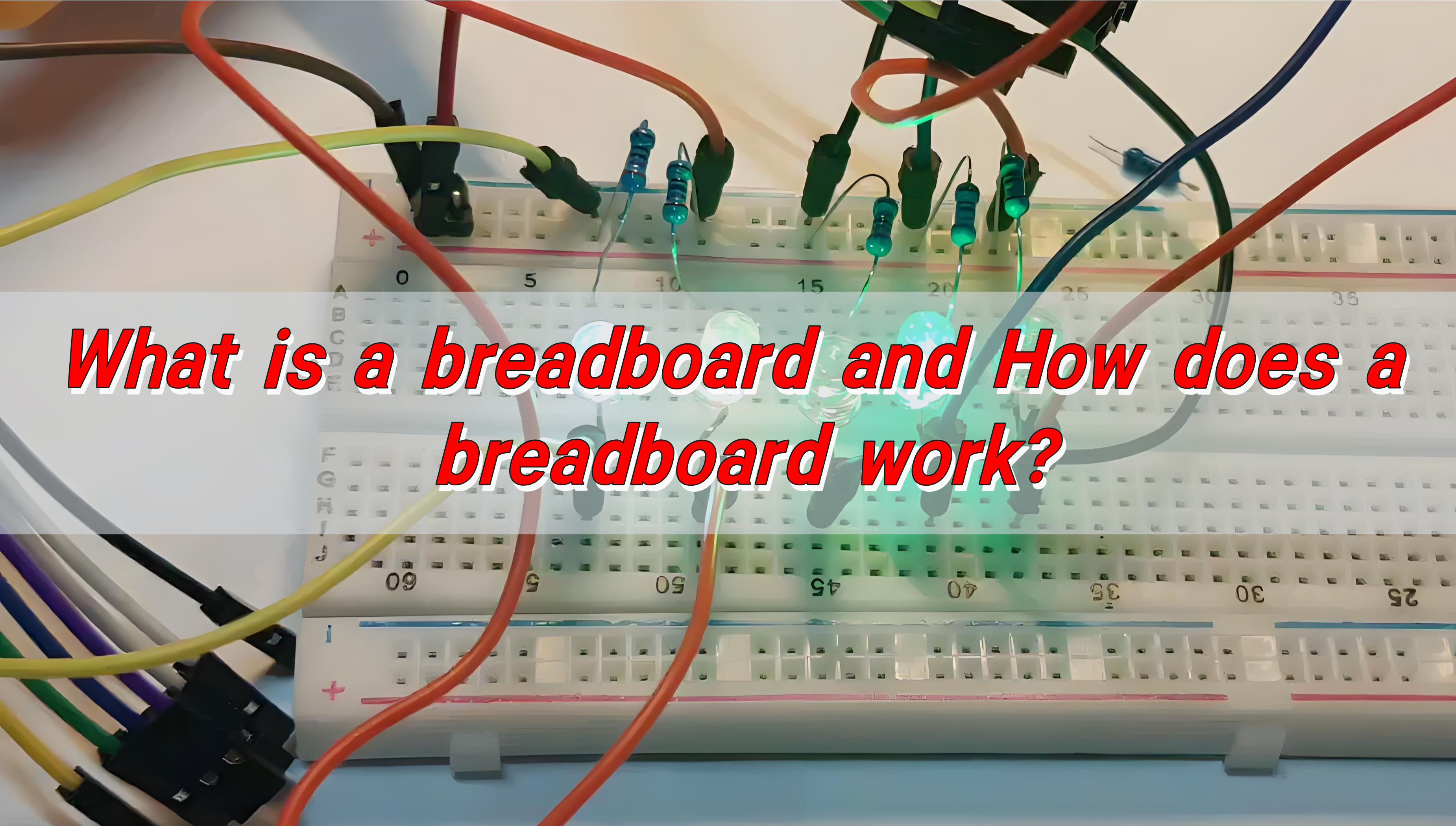
What is a Breadboard?

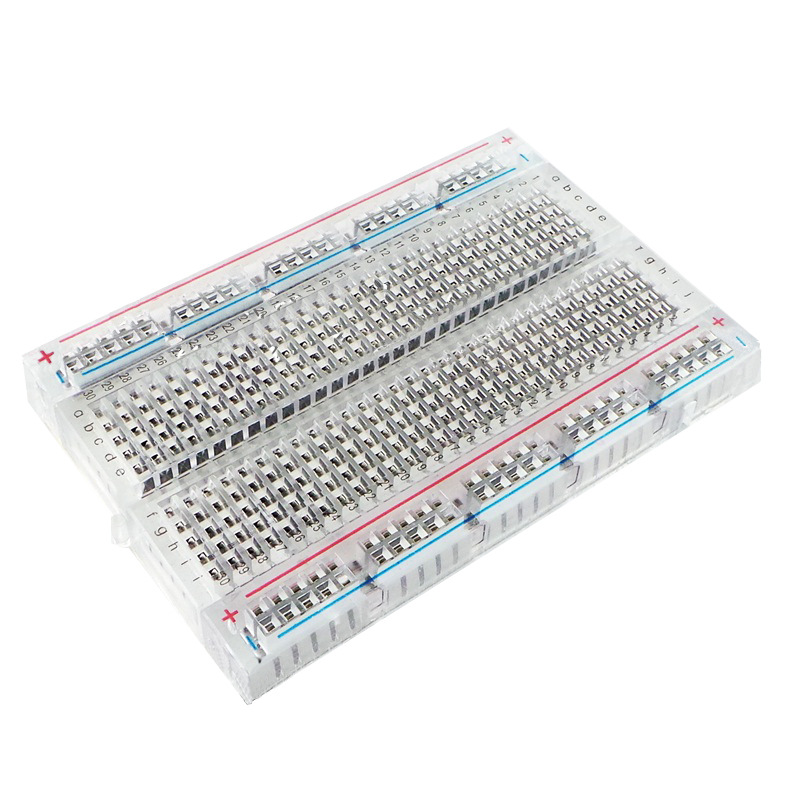
A breadboard is a reusable platform for building temporary electronic circuits. It consists of a rectangular plastic board with a grid of small holes, into which components such as resistors, capacitors, transistors, and integrated circuits (ICs) can be inserted. These holes are connected internally by thin metal strips that create an electrical path without requiring soldering.

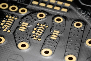
The biggest advantage of a breadboard is its flexibility. Unlike traditional PCBs, where components must be soldered, a breadboard allows for quick modifications. This makes it perfect for testing new circuit ideas, troubleshooting problems, and making iterative design changes without permanently fixing components in place.

What’s Inside a Breadboard?

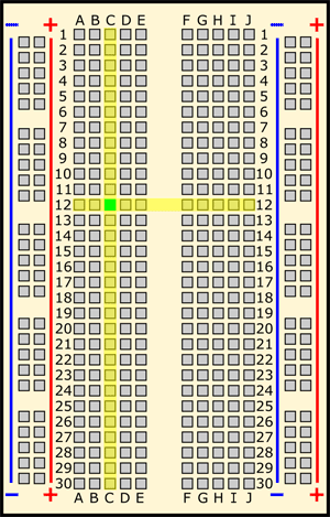
Though a breadboard appears simple on the outside, its internal structure is what makes it work efficiently. Underneath the surface, it has rows of conductive metal strips that connect certain holes together.

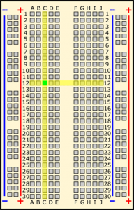
A standard breadboard is divided into three main sections:

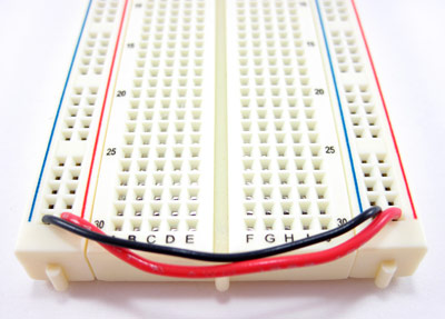
  • Power Rails: These are the long horizontal strips on both sides of the board, usually marked with red and blue lines. They are used to distribute power (positive and negative voltage) across the board, making circuit connections easier.
  • Terminal Strips: These are the main working area where most of the components are placed. Each row of five holes is electrically connected, allowing for easy placement and wiring of circuit elements.
  • Central Divider: The middle gap on a breadboard separates the two halves, which is especially useful for placing integrated circuits (ICs). This ensures that each pin of the IC remains isolated from the others unless explicitly connected with wires.

How Does Current Flow in a Breadboard?

When a component is inserted into a row, it automatically becomes connected to other components within the same row. However, the middle divider prevents direct connections across the board, requiring jumper wires for cross-board connections.

The power rails run vertically, meaning that any component connected to the power strip has access to the same voltage supply. By carefully arranging components and jumper wires, circuits can be created and modified without the need for soldering or permanent wiring.

How does a breadboard work?

The working principle of breadboard is based on the clever layout of internal metal strips. The core of the breadboard is that the circuit can be quickly built without soldering. The jacks on the board are connected by metal strips arranged in parallel at the bottom. Every five holes form a conductive path. When the component pins or wires are inserted into the same group of holes, they can be turned on.

The groove in the center divides the panel into two parts, which are used to insert dual in-line integrated circuits (DIP) to ensure that the pins will not short-circuit. The vertical power rails (marked with “+” and “-“) on both sides provide unified power supply for the entire circuit. The holes on the same side are connected by internal metal strips. When in use, the power rails need to be connected with wires to distribute power.

When building a circuit, it is necessary to plan the position of the components according to the circuit diagram, insert the pins into the corresponding jacks and pay attention to the polarity. Jumpers are used to connect different groups of holes. It is necessary to avoid jumping integrated circuits or overlapping wires. When experimenting, the power supply should be disconnected before operating the components to prevent short circuits.

Breadboards are divided into solderless, single-sided and combination types. The solderless type is portable and suitable for simple experiments, while the combination type supports complex projects but is larger in size. When using, please pay attention to the thickness of the component pins (no more than 0.8mm). It is recommended to connect the wires horizontally and vertically to facilitate testing.

How to Use a Breadboard?

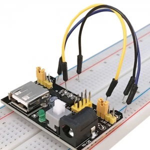
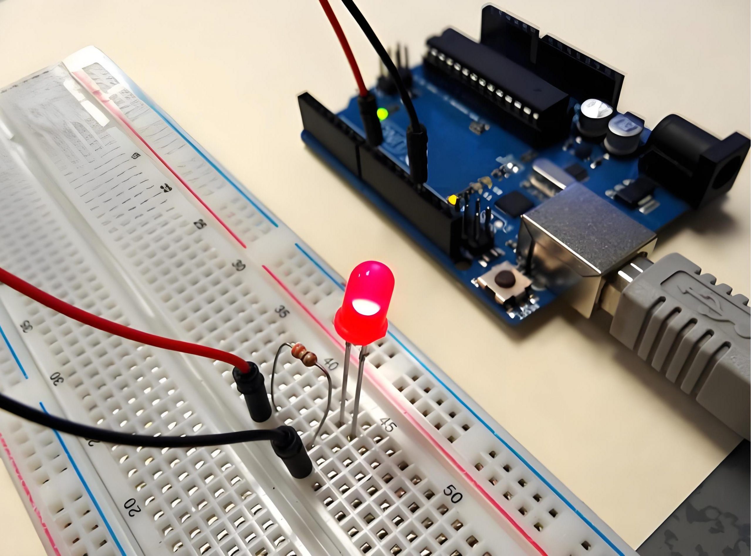
To begin, you first need a power source, such as a battery or a power adapter. The positive and negative terminals should be connected to the power rails to ensure consistent voltage distribution.

Next, components such as resistors, LEDs, transistors, and capacitors can be placed in the terminal strips. Each component should be positioned in a way that allows proper current flow. To complete the connections, jumper wires are inserted to link different components together, forming a functional circuit.

Once the circuit is assembled, the power supply is activated, allowing the circuit to operate. This flexibility makes breadboards invaluable for rapid prototyping and troubleshooting.

What Are the Lines on a Breadboard?

The lines on the breadboard indicate its internal connections. These markings make it easier to plan the layout of the circuit.

  • Power Rail Lines (Red and Blue): The red line represents the positive voltage, while the blue line represents the negative or ground connection.
  • Horizontal Row Markings: These indicate that all the holes within a row are electrically connected.
  • Central Divider: This is a key feature that separates two halves of the breadboard, preventing direct electrical connections between them unless linked with wires.

How Much Current Can a Breadboard Handle?

Breadboards are not designed for high-current applications. Most standard breadboards can safely handle around 0.5A to 1A of current. Going beyond this limit can cause overheating, loose connections, or even damage the breadboardā€™s internal metal strips.

What is a breadboard and How does a breadboard work?

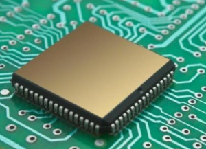
For high-power circuits, using a PCB or soldered perf board is recommended to ensure durability and efficiency.

What Are the Types of Breadboards?

Breadboards come in different types, each suited for specific applications. The most common types include:

  • Solderless Breadboards: These are the most widely used, featuring removable and reusable connections, making them ideal for prototyping.
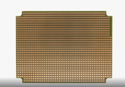
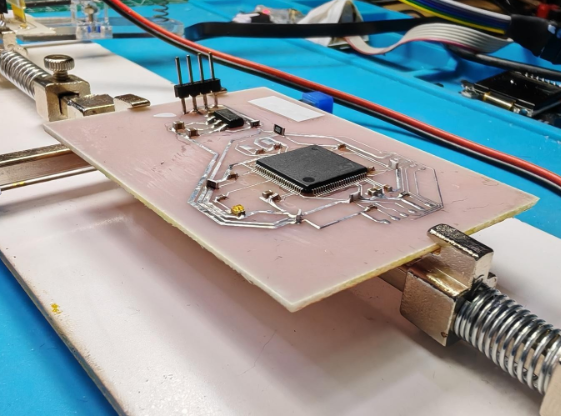
  • Solderable Breadboards: These provide a more permanent solution by allowing components to be soldered onto them after prototyping is complete.
  • Stripboards (Veroboards): These contain continuous copper tracks that can be cut as needed to customize circuit layouts.
  • Mini Breadboards: These are compact and perfect for small-scale circuits or portable electronic projects.

What Are the Disadvantages of a Breadboard?

Despite their versatility, breadboards do have some limitations:

  • Limited Current Capacity: They are not suitable for high-power applications.
  • Unreliable for High Frequencies: The internal resistance and capacitance can affect signals above 10MHz, making them unsuitable for RF applications.
  • Loose Connections: Components and wires can become unstable, leading to intermittent circuit failures.

For more permanent and high-performance applications, PCBs are the best choice.

What is the Frequency Limit of a Breadboard?

Breadboards are best suited for low-frequency circuits. Due to their internal capacitance and resistance, they typically function reliably below 10MHz. Above this range, signal integrity issues arise, causing unwanted noise, interference, and potential malfunctions.

What is a breadboard and How does a breadboard work?

For high-frequency applications, custom PCBs or RF-specific boards are the recommended alternatives.

Conclusion:

A breadboard is a must-have for anyone working with electronics. It allows fast, flexible, and cost-effective circuit building.

Their reusability, affordability, and ease of use make them the perfect choice for prototyping. However, for high-current or high-frequency applications, PCBs are the better alternative. For custom PCB solutions, contact sales@bestpcbs.com

You may also like

What is 95x64mm Strip Board? – Best Technology
Friday, September 13th, 2024

Definition of a 95x64mm Strip Board

The 95x64mm strip board, commonly known as stripboard or veroboard, is a versatile tool used in PCB prototyping. This type of board is pre-drilled with holes arranged in a grid pattern, with copper strips running parallel to one side. The size, 95x64mm, refers to its dimensions: 95 millimeters in length and 64 millimeters in width.

A 95x64mm strip board is a specific size of stripboard. It’s a board with a grid of holes and copper strips that are connected to facilitate the easy construction of electronic circuits. The copper strips can be cut and modified to create connections between different components, making it an invaluable tool for hobbyists and engineers alike.

What is 95x64mm Strip Board? - Best Technology

How to Cut a Stripboard to Size?

Cutting a stripboard to size is essential when working on custom electronic projects, as the default size of the board might not always fit your design requirements. While the process may seem simple, precision is important to ensure a clean cut and a properly functioning circuit. Hereā€™s a step-by-step guide on how to cut a stripboard efficiently:

1. Measure the Required Size

Before making any cuts, it’s crucial to measure the exact size of the stripboard you need for your project. Use a ruler or measuring tape to determine the length and width of the area you will be working with.

After measuring, use a pencil or fine-tip marker to draw cutting lines on the board. Itā€™s essential that the lines are precise and straight. You can use the pre-drilled holes on the stripboard as a guide, ensuring that your cuts are aligned with the rows and columns of the board.

2. Prepare the Work Area

Set up your workspace to ensure that you have a safe and stable area for cutting. Place the stripboard on a flat, stable surface, such as a cutting mat or a workbench. To avoid slipping while cutting, use clamps or a vise to secure the stripboard in place.

3. Cutting Tools

Choose the right tool for the job. A few common tools for cutting a stripboard include:

  • Fine-toothed hacksaw: Ideal for making precise cuts through the stripboard material without damaging the copper strips.
  • Rotary tool (Dremel): A rotary tool with a cutting wheel can make cleaner and more controlled cuts. Itā€™s especially useful for intricate or delicate work.
  • Score and snap method: For small, simple cuts, you can score the board with a sharp utility knife along the marked lines. Once scored deeply, you can snap the board along the cut line.

4. Cut Carefully

Once your stripboard is secure and you have chosen the right tool, itā€™s time to cut. Begin by gently sawing along the marked line. Use steady, even pressure, allowing the saw to do the work. Avoid rushing the cut, as this could lead to uneven or jagged edges. For more precise cuts, guide the rotary tool along the cutting line with steady pressure. The rotary tool can provide smoother edges, but take care to maintain control over the tool for safety and accuracy.

5. Finish the Cut

After the board has been cut, you may notice that the edges are rough or uneven. Smoothing the edges will prevent accidental shorts or damage to the boardā€™s components.

  • File the edges: Use a fine-grit file or sandpaper to carefully smooth out the rough edges of the board. This step is particularly important if you are working with sensitive components or high-density circuits, as sharp edges can lead to unwanted contact with other parts.
  • Check the copper strips: After smoothing the edges, inspect the copper strips on the cut board. Ensure that no copper traces have been damaged during the cutting process. If necessary, you can use a small utility knife or a file to clean up any rough spots near the copper strips.
What is 95x64mm Strip Board? - Best Technology

6. Cutting Strips (Optional)

In many cases, youā€™ll also need to cut the copper strips on the underside of the board to isolate specific circuits or prevent unwanted connections. Use a small drill bit, sharp knife, or strip cutter to make small breaks in the copper strips where needed. Carefully break the strip without damaging the surrounding area. These cuts should align with your circuit design to ensure proper functionality.

Difference Between a Strip Board and a Breadboard

While both strip boards and breadboards are used for prototyping, they have distinct differences:

Strip boards have fixed copper strips on one side, which makes them suitable for permanent or semi-permanent circuit assembly. They require soldering to connect components.

Howevery, breadboards are used for temporary circuit designs. They have a grid of holes that allow for easy insertion and removal of components without soldering. They are ideal for testing and experimenting with different circuit configurations.

What is 95x64mm Strip Board? - Best Technology

What Size is a Stripboard?

Stripboards come in a variety of sizes, allowing engineers, hobbyists, and professionals to choose the right one for their projects. A standard stripboard typically measures around 100x160mm, but smaller or larger sizes are available depending on the complexity and scope of the circuit being designed. One of the most commonly used sizes for prototyping is the 95x64mm stripboard, which offers a compact but functional area for small to mid-range circuits, like:

1. 25 x 64 mm: Has 9 rows and 25 holes

2. 64 x 95 mm: Has 24 rows and 37 holes

3. 95 x 127 mm: Has 36 rows and 50 holes

4. 50 x 80 mm: Also known as the ST1 StripBoard, this is 1.97 x 3.15 in and 1/16 in thick

5. 160 x 100 mm: A common size in the United Kingdom

6. 160 x 233 mm: A standard double height (6U) Eurocard/VME size, which is 9.2 in wide, 6.3 in long, and 1/16 in thick

Stripboards are prototyping boards made from insulating material, like fiberglass or resin-bonded plastic. One side of the board has parallel copper strips that are typically spaced 2.54 mm apart.

Layout of a Stripboard

The layout of a stripboard is quite functional:

Copper Strips: One side of the board has copper strips running parallel to each other. These strips can be cut to create breaks and allow for more flexible circuit designs.

Holes: The board is drilled with a grid of holes that line up with the copper strips. Components can be inserted into these holes, and connections can be made by soldering to the copper strips.

Breaks and Jumps: To customize the circuit, you can cut the copper strips or use wire “jumps” to make connections that donā€™t follow the copper strips.

Difference Between Donut Board and Strip Board

Board Structure and Layout

Donut boards, also known as perfboards, have isolated copper pads around each hole, meaning no automatic connections between adjacent holes. In contrast, stripboards have parallel copper strips that connect rows of holes, allowing predefined electrical connections.

Component Placement

On donut boards, components can be placed freely without layout restrictions. Stripboards, however, require components to align with the copper strips, which can limit layout flexibility but simplify organization for linear designs.

Wiring and Soldering

With donut boards, each connection must be made manually, which increases soldering time. Stripboards reduce wiring by offering predefined connections, but cutting the strips may still be necessary for more intricate designs.

Fault Diagnosis

Diagnosing faults on a donut board is easier because each connection is made manually, allowing clear visibility of potential issues. On a stripboard, diagnosing faults can be more difficult due to the copper strips, which may cause unintentional short circuits.

As an advanced PCB and PCBA manufacturer, we have over 18years manufacturing experience. “High mixed, low volume, high quality and fast delivery” is our core values. 70% of our employees are the core memebers in our company, they have professional and rich skills in this industry. Contact us for your PCB projects!

You may also like

What is a breadboard & What is it used for?
Monday, September 9th, 2024

In the vast world of electronics, there is a seemingly ordinary but extremely important tool, the breadboard. The breadboard is like a silently dedicated assistant to electronic engineers, building a bridge for electronic enthusiasts and professionals to realize their creativity. So, what exactly is a breadboard? What is its indispensable use?

What is a breadboard?

A breadboard is a board designed and manufactured for solderless experiments on electronic circuits. It has many small jacks, allowing various electronic components to be inserted or removed as needed, eliminating the soldering steps, saving circuit assembly time, and components can be reused, which is very suitable for electronic circuit assembly, debugging and training.

What is a breadboard & What is it used for?

The original intention of the breadboard was to encourage innovation and simplify the learning process of electronic circuits. Its main features include:

  • No soldering design: users can directly insert electronic components into the jacks of the breadboard without soldering, which greatly reduces the difficulty and complexity of electronic circuit production.
  • ā€ŒComponents are reusableā€Œ: Due to the solderless design, users can replace or adjust components in the circuit at any time without re-soldering, which is very beneficial for experiments and learning.
  • ā€ŒSuitable for all kinds of electronic componentsā€Œ: Whether it is resistors, capacitors, transistors or integrated circuits, they can be easily inserted into the sockets of the breadboard for experiments and tests.
  • ā€ŒSimple structureā€Œ: Breadboards are usually made of plastic blocks and contain a matrix of electrical sockets inside. These sockets are connected within the board, usually in rows of five sockets, forming a complete circuit path.

Why is it called a breadboard?

The reason why the breadboard got its name can be traced back to the era of vacuum tube circuits. At that time, most of the circuit components were large in size, and people usually fixed them to a piece of bread-cutting wood for connection by screws and nails. As the size of circuit components decreased, the name of the breadboard remained.

What is a breadboard & What is it used for?

The origin of this name reflects the historical evolution and technological progress in the field of electronic production, and also reflects the intimacy and recognition of electronic production enthusiasts for this tool.

The original intention of the design of breadboard is to facilitate the assembly, debugging and training of electronic circuits. By providing many small jacks, various electronic components can be inserted or unplugged at will, thus eliminating the trouble of welding, saving the assembly time of the circuit, and the components can be reused, which is very suitable for the non-welding experiment of electronic circuits.

What is a breadboard used for?

Breadboards are mainly used for the design and manufacture of non-welding experiments of electronic circuits. ā€Œ

A breadboard is a board designed and manufactured for the non-welding experiment of electronic circuits. Its characteristics are that there are many small jacks on the board, allowing various electronic components to be inserted or unplugged at will as needed, thus eliminating the welding process and saving the assembly time of the circuit.

What is a breadboard & What is it used for?

In addition, since the components can be reused, breadboards are very suitable for the assembly, debugging and training of electronic circuits. This tool is a must-have for electronic production enthusiasts, and is widely used in electronic engineering, communication engineering, automatic control and other fields.

In practical applications, breadboards can be used for simulation testing and verification in the circuit design stage, as well as for transferring circuits to PCB boards for mass production in the production and manufacturing stage.

In the fields of education and research, breadboards help students and researchers better understand electronic technology and circuit design principles. It can also be used for the development and production of DIY electronic products, robots and other fields, and has a wide range of application prospects.

What types of breadboards are there?

1. Solderless breadboard:

This is the most common type. It consists of many small jacks inside, and the circuit is connected by inserting the pins of electronic components. No soldering is required, which is convenient and fast, suitable for beginners and quick circuit construction and debugging.

There are different specifications and sizes, such as small breadboards are suitable for simple circuit experiments, and large breadboards can accommodate more components to build more complex circuits.

2. Solderless breadboard:

The function is similar to that of the solderless breadboard, and electronic components can be connected without soldering. Usually with colored marking lines or areas, it is easy to distinguish different circuit parts and plan component layout.

Some solderless breadboards also come with power bars and ground bars, which are convenient for providing power and ground connections for the circuit.

3. Multi-hole breadboard:

There are more jacks and a denser layout. More electronic components can be connected, which is suitable for building complex circuits.

Some multi-hole breadboards are also designed with special structures, such as grooves or slots, to facilitate the fixing of wires and components and make the circuit more stable.

4. Breadboard with power supply

The integrated power module can directly provide stable power to the circuit without the need to connect an additional power adapter or battery pack.

The power supply part usually has an adjustable voltage function to meet the power requirements of different electronic components.

5. Transparent breadboard

Made of transparent materials, it is convenient to observe the connection status and component layout inside the circuit, which is very helpful for teaching and circuit debugging.

The appearance of the transparent breadboard is beautiful, which can increase the fun and visualization of circuit construction.

What is a “solderless” breadboard?

A solderless breadboard (also called a solderless test board) is a method that provides convenient interconnection of electronic components without the need for soldering. ā€ŒThis breadboard consists of a series of U-shaped metal contacts that are located below the hole grid in the electrically insulating shell.

The component leads and the wire segments inserted through the holes are held under spring tension by the contacts below, thus achieving a solderless connection. Solderless breadboards are particularly suitable for electronic circuit experiments in hobby, education or development environments because they allow users to quickly and easily build and reconfigure circuits while saving the time and cost of soldering.

In addition, solderless breadboards also support the reuse of components, which is very beneficial for learning and training. However, it should be noted that although solderless breadboards provide great convenience, they do not provide a mechanically sturdy interconnection, have limited power handling capabilities, and are not suitable for high-speed circuit applications.

What are the advantages and disadvantages of a breadboard?

The advantages of breadboards are:

1. Convenient and fast operation:

  • No need to solder, electronic components can be directly inserted into the jacks of the breadboard for circuit connection, which greatly saves the time and workload of circuit construction.
  • If a connection error is found during the insertion of the component, the component can be easily pulled out and reinserted without damage, reducing the cost and risk of circuit construction.

2. High safety:

  • Compared with soldered circuits, breadboards do not have safety issues such as burns and electric shocks that may occur during soldering, and are particularly suitable for beginners and students.
  • There is no need to worry about components being damaged due to improper soldering, which reduces safety hazards in circuit experiments.

3. Suitable for beginners:

  • For beginners of electronic circuits, breadboard is an ideal learning tool. It can help beginners quickly understand the basic principles and connection methods of circuits, enhance the perceptual understanding of electronic circuits through practical operations, and improve the interest and efficiency of learning.

4. Easy to observe and debug:

  • The structure of the breadboard is relatively simple, and the circuit connection is clearly visible, which is convenient for users to observe the connection of the circuit and the layout of components.

The advantages of breadboard are:

1. Poor connection stability:

  • The contact between the jacks on the breadboard and the component pins may not be tight enough, and it is easy to have a virtual connection. Especially after transportation, movement or long-term use, the jacks may become loose, resulting in unstable circuit connection and affecting the normal operation of the circuit.

2. Not suitable for complex circuits:

  • The number and layout of the jacks of the breadboard are limited. When the number of components in the circuit is large or the circuit structure is complex, the breadboard may not provide enough jacks to connect all the components, limiting the scale and complexity of the circuit.
  • When there are many connecting wires on the breadboard, it is easy to have chaotic lines, which increases the difficulty of circuit debugging and troubleshooting.

3. Poor high-frequency performance:

  • The structure and material of the breadboard determine that its high-frequency performance is poor, and it is not suitable for the transmission and processing of high-frequency signals. In high-frequency circuits, the transmission of signals will be affected by the jacks and connecting wires on the breadboard, resulting in signal distortion, attenuation and other problems.

4. Limited current carrying capacity:

  • The current carrying capacity of the connecting wires and jacks on the breadboard is limited. For high-power electronic components, it may not provide enough current, causing the components to not work properly or damage the breadboard.

Conclusion:

Breadboards are an indispensable tool in the world of electronics. From experiments to troubleshooting, breadboards are an indispensable part of circuit design. They can easily handle modifications, are cost-effective, and are reusable, making them a mainstream product in the electronics field.

You may also like