Rectifier PCB is a circuit board used to convert AC power into DC power. Its core function is to achieve the form conversion of electrical energy through a rectifier circuit (usually composed of components such as diodes). This type of PCB is widely used in power adapters, chargers and various electronic devices to provide stable DC power for the devices.
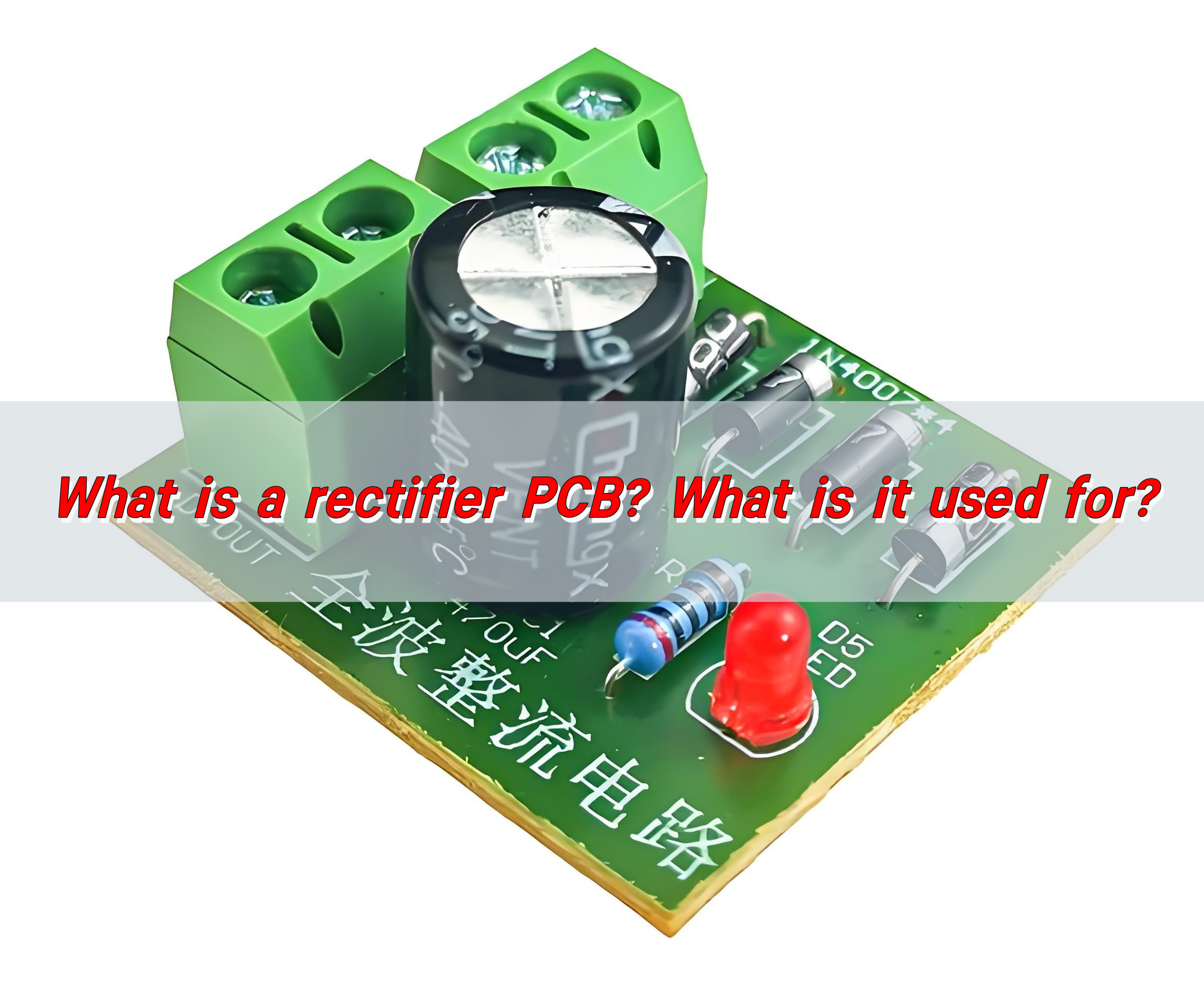
What is a Rectifier PCB?
A rectifier PCB is a specialized type of printed circuit board designed to house rectifier components like diodes, capacitors, and resistors, which together convert AC power into DC power. These PCBs often feature layouts optimized for heat dissipation, component placement, and efficient current flow.
Rectifier PCBs are crucial in devices where AC power needs to be transformed into a stable DC voltage, like in power supplies, battery chargers, and DC motors.
Rectifiers themselves come in several configurations, but the most common are half-wave and full-wave rectifiers. Each type has different designs and methods for conversion, and the PCB layout will vary based on the specific rectifier type being used.
What Does a Rectifier Board Do?
At its core, a rectifier board performs one job: converting AC to DC. But this simple task is essential to countless devices.
In an AC circuit, the current alternates direction periodically, making it unsuitable for devices that require a constant voltage to function, such as LED lights, batteries, and most electronic circuits.
Rectifiers use diodes to allow current to flow in only one direction, converting the AC input into a smoother DC output.
Depending on the rectifier configuration, a rectifier PCB can smooth out the power through additional filtering components like capacitors. This results in a cleaner DC output with minimal ripple, which is crucial for sensitive electronic devices that cannot tolerate fluctuations in voltage.
What Are the Types of Rectifier PCB?
There are several types of rectifier PCBs, each designed for different purposes. The main difference between them lies in the configuration of the rectifying diodes and how they handle the AC input signal.
- Half-Wave Rectifier PCB
A half-wave rectifier PCB is the simplest design. It uses a single diode to convert the positive half of the AC waveform into a DC signal while blocking the negative half. This results in a highly pulsating DC signal with significant ripple, making it less efficient for many applications but suitable for low-power circuits.
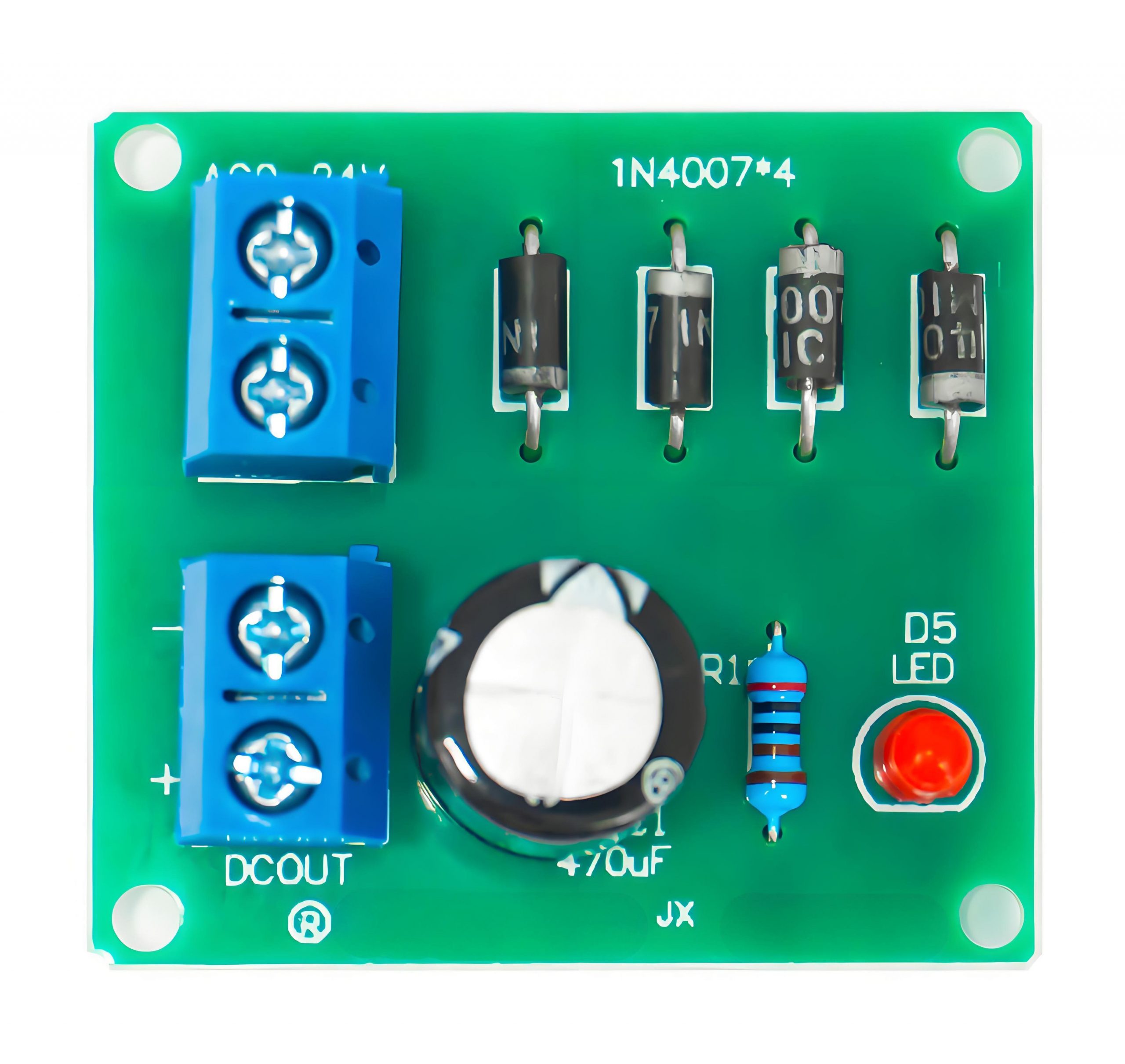
- Full-Wave Rectifier PCB
A full-wave rectifier PCB uses two diodes or a bridge rectifier configuration to convert both halves of the AC waveform into DC. The output is smoother and more consistent than that of a half-wave rectifier. This makes full-wave rectifiers more efficient for medium to high-power applications.
The full wave rectifier PCB layout is more complex than the half-wave design due to the need for more components, but it offers greater efficiency and stability.
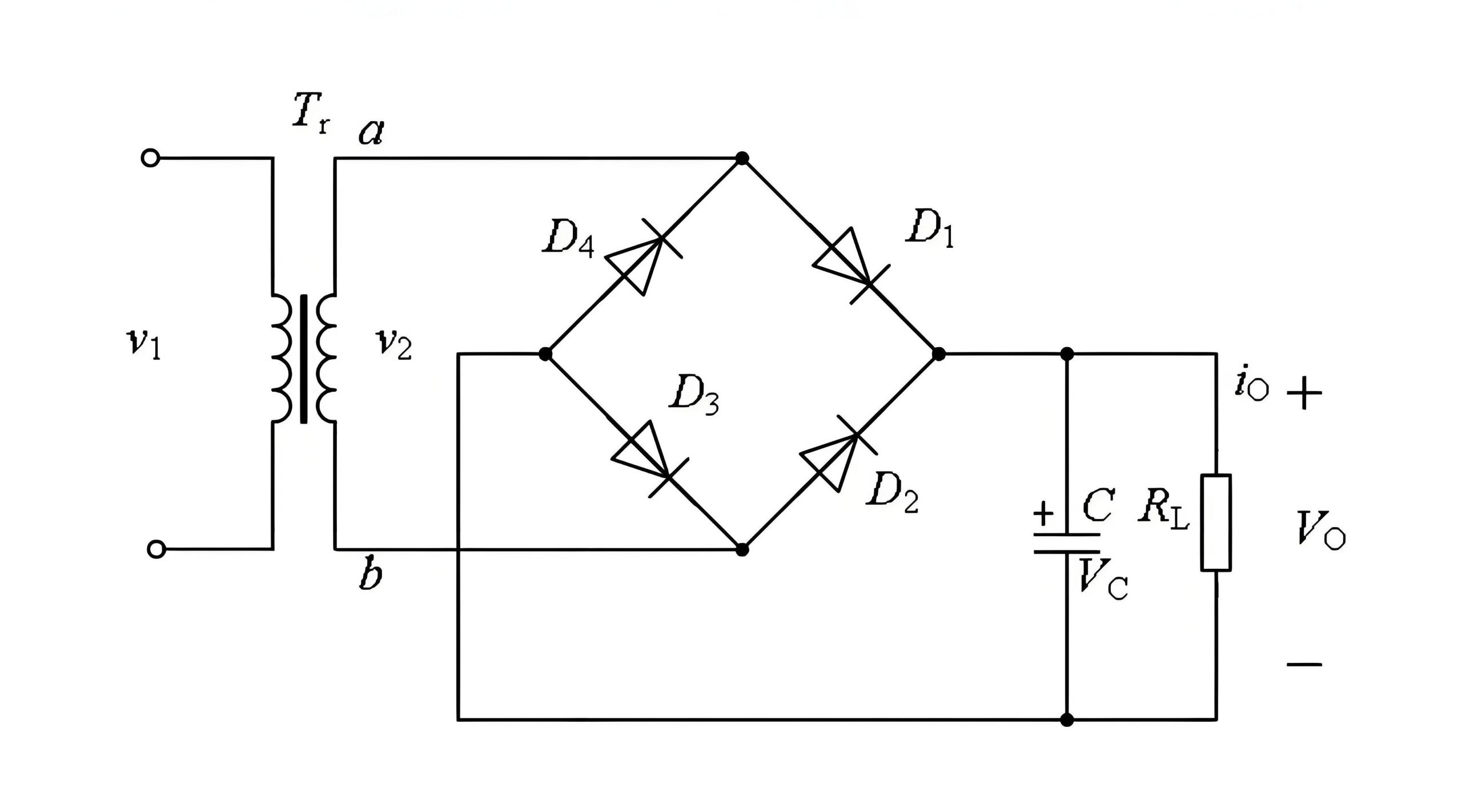
- Bridge Rectifier PCB
A bridge rectifier PCB board uses a bridge of four diodes to convert the AC input into a fully rectified DC output. This configuration is more efficient than a half-wave rectifier and can be used with both single-phase and three-phase AC supplies. It’s commonly used in power supply units and higher-power devices due to its reliability and efficiency.
Each type of rectifier PCB serves different applications depending on the required current, voltage, and ripple tolerance.
Can a Rectifier PCB Convert DC to AC?
Rectifier PCBs are designed to convert AC into DC, not the other way around. This is a fundamental property of rectification — it only works in one direction.
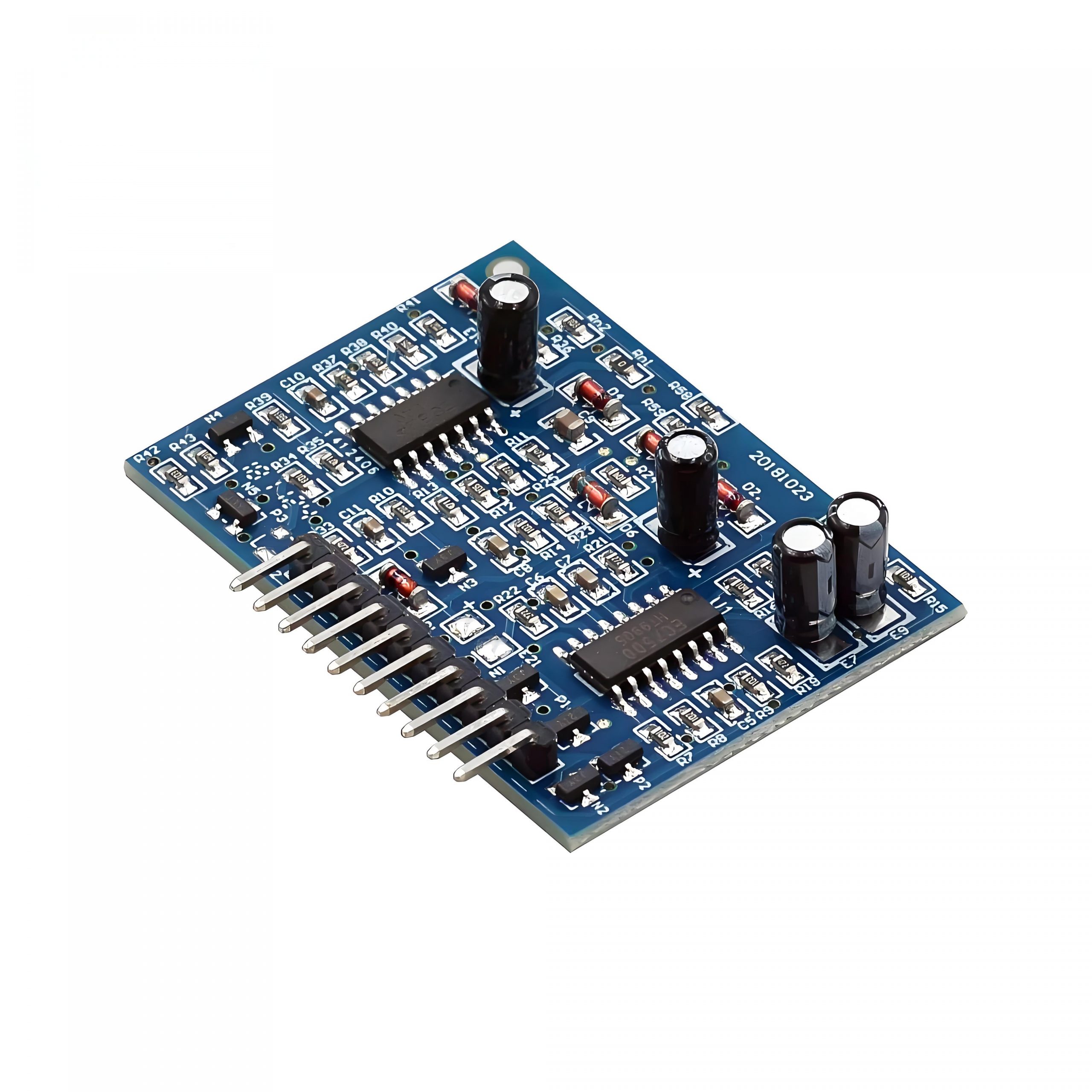
To convert DC to AC, you would need an inverter PCB. Inverters work by using a different set of components, typically transistors, to change the polarity of the current. They play the opposite role of rectifiers by enabling DC devices to run on AC power.
Converting DC to AC requires designing a circuit based on an inverter PCB rather than a rectifier PCB. These two components work together in many power systems but play very different roles.
What is the Difference Between Rectifier PCB and Inverter PCB?
As mentioned, rectifier PCBs and inverter PCBs perform opposite tasks. A rectifier PCB converts alternating current (AC) to direct current (DC), while an inverter PCB does the opposite, converting DC to AC.
- Rectifier PCBs: These are primarily used when you need to transform AC from a power source (such as the grid) into DC, which is required by most electronic devices. The most common application for rectifier PCBs is in power supplies, where AC from a wall outlet is converted to DC to power devices like computers, LED lights, and mobile phones.
- Inverter PCBs: These are used in renewable energy systems (like solar power) where DC from solar panels needs to be converted into AC to be used in homes or businesses. Inverters are also found in devices that convert battery power (DC) to AC for powering AC appliances.
In short, the key difference lies in the direction of current flow: rectifiers convert AC to DC, and inverters convert DC to AC.
What Are the Applications of Rectifier PCB?
Rectifier PCBs are used in a variety of industries where efficient conversion of AC to DC is required. Some key applications include:
- Power Supplies: Most electronic devices, including computers, televisions, and mobile phone chargers, rely on rectifiers to convert the AC from wall outlets into usable DC power.
- LED Lighting: LEDs typically run on DC voltage, and rectifier PCBs ensure that the AC supplied to the lights is converted into a stable DC signal, allowing the lights to function correctly.
- Battery Chargers: Rectifiers are essential in battery charging circuits. They convert AC from the grid into DC to charge batteries used in a variety of devices, from power tools to electric vehicles.
- DC Motors: Many motors, especially those in robotics and electric vehicles, require DC voltage to operate. Rectifier PCBs ensure that the AC power from a grid or generator is appropriately converted to DC.
Power Conversion in Industrial Electronics: Rectifier PCBs are used in industrial machines, power equipment, and even some renewable energy applications to convert AC to DC.
Advantages and Disadvantages of Full Wave Rectifier PCB
The full wave rectifier PCB offers several advantages over its half-wave counterpart, but there are also some limitations.
Advantages:
- Higher Efficiency: Full-wave rectifiers use both halves of the AC signal, making them more efficient in converting AC to DC.
- Lower Ripple: Because full-wave rectifiers convert both positive and negative halves of the AC signal, they produce a more consistent DC output with less ripple compared to half-wave designs.
- Better Utilization of Input Signal: Since both halves of the AC waveform are used, the system’s overall efficiency improves, allowing the circuit to perform better with the same input.
Disadvantages:
- Complexity: The full-wave rectifier PCB layout is more complex than the half-wave rectifier, requiring more diodes or a bridge rectifier configuration.
- Higher Cost: With additional components and a more complicated design, full-wave rectifier PCBs tend to be more expensive than half-wave options.
Conclusion:
Rectifier PCBs are indispensable in today’s electronics, converting AC into DC for use in everything from power supplies to LED lights. Whether you need a simple half-wave rectifier or a more complex full-wave rectifier PCB, choosing the right design can ensure the efficient performance of your devices.
If you’re looking for high-quality rectifier PCB designs and manufacturing services, feel free to contact us at sales@bestpcbs.com