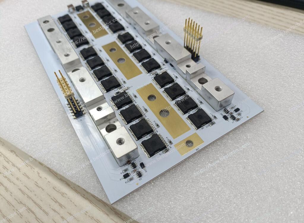
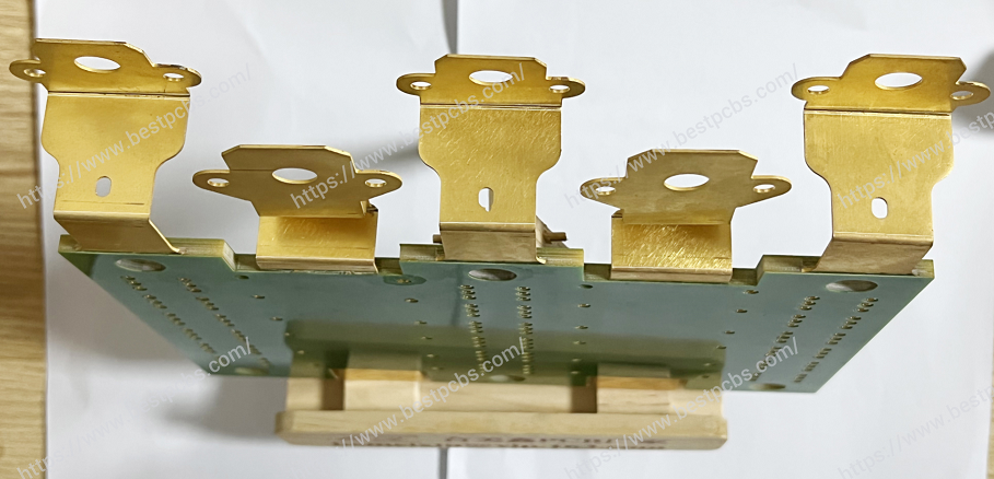
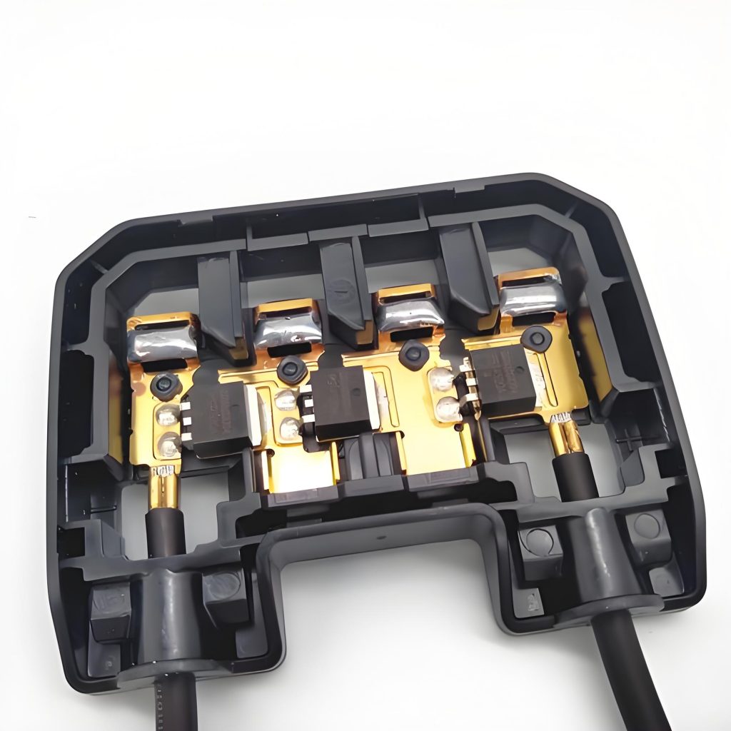
What is Bus Bar PCB for Battery? The battery busbar PCB is a circuit board used for battery pack connection and management. It is mainly composed of signal acquisition components (such as FPC, PCB, FFC, etc.), plastic structural parts, copper and aluminum bars, etc., and is connected into a whole through processes such as hot pressing or riveting.
What is a Battery Bus Bar?
A battery bus bar is a conductive strip or block that connects different battery cells or battery packs to each other, creating an efficient and secure path for current to flow.
In battery systems, especially those used in electric vehicles (EVs) and renewable energy storage systems, bus bars serve as the main distribution point for the electrical current.
Typically, bus bars are designed to handle high current loads and are placed between multiple battery cells or batteries in series or parallel configurations. The goal is to create a stable connection that allows for optimal performance, minimized resistance, and safe operation.
Battery bus bars are used in systems where batteries need to be connected in such a way that the current flows seamlessly, efficiently, and safely from one cell or pack to another. They are often made from conductive materials that minimize resistance while ensuring durability and safety under high load conditions.
What is a Bus Bar in PCB?
A bus bar in PCB design refers to a conductive path that carries high electrical current across the board. Unlike typical trace wiring, which is designed for low- to medium-current applications, bus bars on a PCB are intended to carry significant amounts of current, often across larger areas of the circuit board.
Bus bar PCBs are used in applications where multiple high-current connections are needed, such as in power electronics, motor drives, and battery management systems. These bus bars act as a pathway for electricity to flow efficiently from one component to another. They are particularly crucial in battery systems, where power distribution needs to be optimized for both performance and safety.
In PCB design, bus bars are created by using thicker copper layers, wider traces, or even copper strips that are physically mounted onto the board. This allows the board to handle higher currents without excessive heating or power loss.
Why Use Bus Bar on PCB?
Using a bus bar on a PCB offers several significant benefits:
- Improved Current Carrying Capacity: Bus bars are designed to handle higher currents than typical PCB traces, allowing them to support more powerful devices without risking overheating or damage.
- Reduced Resistance: Since bus bars typically have a larger surface area compared to regular PCB traces, they reduce the overall resistance within the circuit. Lower resistance means less energy lost in the form of heat and more efficient power distribution.
- Better Thermal Management: Bus bars can distribute heat more evenly due to their wider, thicker structure. This helps in managing the heat generated by high-current flow, ensuring the PCB doesnât overheat and cause damage to the components.
- Simplified Design: By incorporating bus bars, designers can reduce the need for complex wiring and interconnections. Bus bars provide a clear, direct path for current, which makes the overall design cleaner and easier to manage.
- Increased Safety: Bus bars help prevent circuit failures by distributing power efficiently and maintaining proper voltage levels across all components. This ensures the PCB and the devices connected to it are protected from power surges and voltage drops.
What are the Pros and Cons of Busbars in PCB?
Like any technology, bus bars in PCB applications come with their advantages and challenges.
Pros:
- High Current Handling: Bus bars can handle much higher currents than conventional traces, making them essential for high-power applications like battery systems, power supplies, and motor controllers.
- Lower Power Loss: With their larger size and improved conductivity, bus bars allow for minimal energy loss due to resistance. This makes systems more efficient.
- Enhanced Durability: Bus bars are typically more robust than regular PCB traces, offering greater durability and resistance to wear and tear, especially in high-stress environments.
- Easier Assembly: Bus bars simplify PCB design and assembly by reducing the need for individual connections between components, making the overall design process cleaner and faster.
- Thermal Management: The larger surface area of bus bars allows for better dissipation of heat, reducing the risk of thermal damage to the board and components.
Cons:
- Increased Board Size: The addition of bus bars requires more space on the PCB, which could be a limitation in compact designs.
- Cost: Due to their size and the materials used, bus bars can increase the cost of the PCB, especially in applications that require high-current handling.
- Design Complexity: While bus bars simplify certain aspects of the design, they can also complicate others, particularly when trying to balance current distribution and thermal dissipation.
Overall, the pros of using bus bars often outweigh the cons, especially in high-power systems where efficiency and safety are critical.
Why is It Called a Bus Bar?
The term “bus bar” comes from the word âbus,â which refers to a central electrical point that distributes power to various components or circuits. The word âbarâ simply refers to the physical shape of the conductor, which is often a flat or rectangular piece of metal. Therefore, a bus bar is essentially a flat, conductive strip or bar used to distribute electrical power.
In PCB applications, bus bars provide the same function as their larger counterparts in electrical distribution systems. They act as a central hub that ensures current is delivered where itâs needed, in a way thatâs efficient and safe.
What Material is Battery Bus Bar?
The material used for battery bus bars is crucial for ensuring efficiency and safety. The most commonly used materials include:
- Copper: Copper is the most popular material for bus bars due to its excellent electrical conductivity. It also offers good corrosion resistance, making it ideal for use in battery systems where performance and longevity are essential.
- Aluminum: While not as conductive as copper, aluminum is a lightweight alternative that can still handle high currents.
- Gold-Plated Copper: In high-end or specialized applications, gold-plated copper may be used for bus bars to enhance conductivity and prevent oxidation. However, this material is generally more expensive.
- Tinned Copper: Tinned copper offers enhanced corrosion resistance, making it suitable for use in environments where moisture or chemicals might be present.
- Brass or Silver: In some cases, brass or silver may be used for specialized applications that require specific properties like high conductivity or low contact resistance.
The choice of material largely depends on the performance requirements, environmental conditions, and budget of the application.
How to Choose a Bus Bar?
Choosing the right bus bar for a PCB, particularly for battery systems, depends on several key factors:
- Current Handling Capacity: The first and most important consideration when selecting a bus bar is the amount of current it needs to handle. Choose a bus bar that is rated for the maximum current expected in the application.
- Material: The material of the bus bar will directly impact its conductivity, durability, and cost. Copper is commonly used due to its excellent conductivity, but other materials like aluminum or gold-plated copper may be used for specific applications requiring resistance to corrosion or enhanced conductivity.
- Size and Shape: Bus bars come in various sizes and shapes, depending on the PCB design and available space. The dimensions of the bus bar must match the PCB layout and provide the necessary current-carrying capacity while fitting within the design constraints.
- Thermal Management: A good bus bar design will take heat dissipation into account. Bus bars should be thick enough to carry the required current without generating excessive heat, and the PCB layout should ensure adequate cooling.
- Mechanical Strength: Bus bars are often subjected to mechanical stresses, especially in applications like electric vehicles or battery packs. Choose bus bars that can withstand vibration and other forces without losing their structural integrity.
- Compliance and Safety: Finally, make sure the bus bar complies with industry standards and safety regulations, particularly if the PCB will be used in critical applications like battery management systems or medical devices.
Conclusionï¼
Bus bar PCBs for battery systems play a crucial role in efficient power distribution. These conductive strips or blocks ensure that current flows smoothly across battery cells and other components, enabling high-current applications like electric vehicles and renewable energy systems to operate safely and efficiently.
BEST Technology is able to build and design busbar PCB according to your specific requirements. If you want to manufacture battery busbar stiffener PCB, please contact us at sales@bestpcbs.com


