
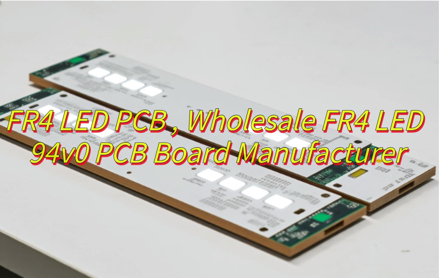
Curious about FR4 LED PCB solution? This guide explores their composition, benefits, thermal management, assembly optimization, and 94v0 compliance testing for LED applications as well as how to choose a wholesale FR4 LED 94v0 PCB board manufacturer.
Best Technology delivers superior FR4 LED PCB solutions especially for high-performance lighting systems, combining rapid prototyping with industrial-grade reliability. Our 48-hour sample service ensures fully tested prototypes with detailed thermal simulations and cross-sectional analysis reports, accelerating product development cycles. Clients benefit from 24/7 engineering support through dedicated technical advisors who optimize designs for thermal resistance ≤2.5°C/W and compliance with UL94V-0 flammability standards. Advanced Tg170+ FR4 substrates and automated optical inspection systems guarantee 99.98% production consistency, while ionic contamination controls maintain <0.75μg/cm² purity for outdoor applications. We specialize in complex multilayer layouts (up to 24 layers) with precision solder masks resistant to harsh environments, backed by RoHS/WEEE certifications for global distribution. From dynamic LED displays to industrial control panels, our end-to-end DFM guidance and failure analysis ensure seamless scaling from prototypes to bulk orders exceeding 50,000 units monthly. Request instant quotes with guaranteed 72-hour response – let our expertise transform your lighting concepts into market-ready solutions. Contact us today: sales@bestpcbs.com if you have any request for FR4 LED PCB.
What Is FR4 LED PCB?
An FR4 LED PCB is a printed circuit board designed for mounting and operating light-emitting diodes (LEDs) using FR4 material as the base substrate. The board consists of a layered structure with a fiberglass-reinforced epoxy resin core, copper traces for electrical connectivity, and a solder mask to protect circuitry. Essential components include conductive pathways connecting LEDs, resistors, and drivers, along with mounting pads for secure component placement. This type of PCB supports electrical signal transmission, distributes power to LEDs, and maintains mechanical stability for the electronic assembly. The design integrates insulation layers to prevent short circuits and ensures reliable performance under standard operating conditions.
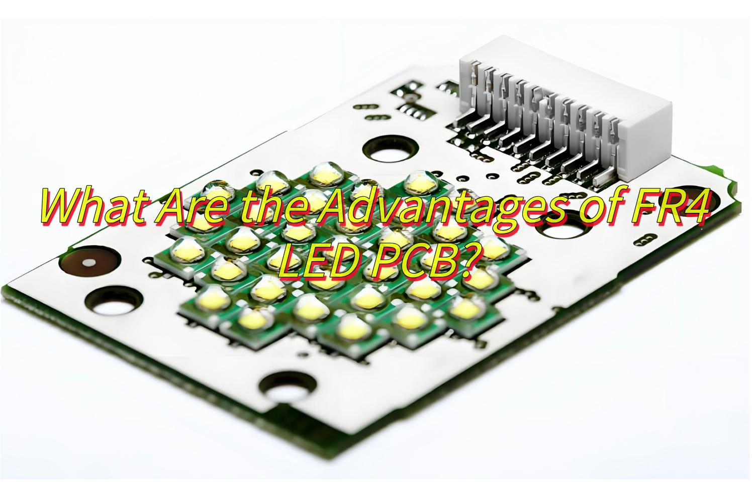
What Are the Advantages of FR4 LED PCB?
- Flame-retardant properties enhance safety by meeting fire-resistance standards.
- Cost-effective production due to standardized materials and manufacturing processes.
- Structural rigidity supports stable LED component mounting without warping.
- Electrical insulation prevents short circuits between conductive layers.
- Compatibility with standard assembly methods simplifies integration into electronic systems.
- Durability withstands moderate thermal stress and environmental exposure.
- Design adaptability allows customization for various circuit layouts and layer counts.
- RoHS compliance ensures environmentally safe material composition.
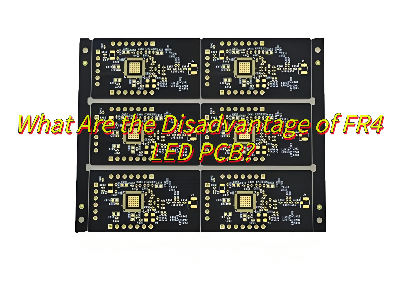
What Are the Disadvantage of FR4 LED PCB?
- Limited thermal conductivity compared to metal core PCB, leading to potential heat buildup in high-power LED setups.
- Reduced mechanical durability under repeated thermal cycling, risking layer separation or warping over time.
- Thicker profile than flexible PCBs, restricting use in compact or bendable lighting designs.
- Lower resistance to moisture absorption in humid environments compared to specialized substrates.
- Performance degradation at sustained temperatures above 130°C, limiting high-temperature applications.
- Higher material expansion rate under heat than ceramics, causing potential solder joint stress.
- Limited suitability for high-frequency LED circuits due to dielectric properties.
- Recycling challenges from mixed material composition complicating eco-friendly disposal.
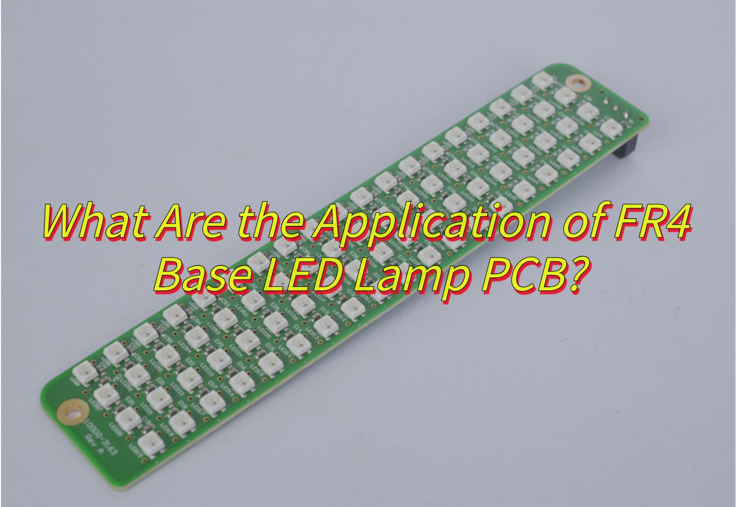
What Are the Application of FR4 Base LED Lamp PCB?
- High-resolution indoor/outdoor displays for advertising boards and stage backdrops, featuring pixel densities ≤1.86mm and refresh rates ≥3840Hz.
- Commercial lighting systems integrating dynamic energy-saving modes that reduce power consumption by ≥60% during idle periods.
- Industrial environments requiring IK10-rated impact resistance and mechanical stability under ≥4800N tensile loads.
- Precision color-critical equipment like medical imaging monitors, achieving color accuracy ΔE≤0.9 and supporting BT.2020/DCI-P3 color spaces.
- Telecommunication infrastructure components including status indicators and control panels, leveraging electrical insulation properties.
- Modular video walls with sub-0.1mm seam tolerances and 99% brightness uniformity for control rooms or broadcast studios.
- 3D/VR compatible displays handling 240Hz refresh rates and 16-bit grayscale adjustments for immersive visual experiences.
- Public transportation information panels maintaining visibility across 175° viewing angles under varying ambient light.
How to Improve the Thermal Design of FR4 LED 94v0 PCB?
Here are some ways to improve the thermal design of FR4 LED 94v0 PCB board:
- Integrate thermal vias under high-power LED chips to transfer heat from component layers to cooling surfaces.
- Increase copper thickness in power planes for better lateral heat spreading across the board.
- Distribute LED clusters with spacing patterns that prevent localized heat concentration.
- Apply thermally conductive epoxy or pads between PCB and aluminum heatsink interfaces.
- Implement forced-air cooling through strategic board positioning in housing vents or fans.
- Optimize trace widths and current paths to minimize resistive heat generation.
- Select LED chips with lower forward voltage characteristics to reduce inherent thermal load.
- Utilize multi-layer stack-ups with dedicated internal heat dissipation channels.
- Pair with moisture-resistant conformal coatings to maintain thermal performance in humid conditions.
- Monitor real-time thermal profiles using embedded sensors for dynamic power adjustment.
How to Choose A Wholesale FR4 LED 94v0 PCB Board Manufacturer?
Here are some methods about how to choose a wholesale FR4 LED 94v0 PCB board manufacturer:
- Verify UL94V-0 flammability certification documentation to ensure compliance with safety regulations for LED applications.
- Confirm bulk production capabilities matching your project scale, checking machinery like automated optical inspection systems.
- Request thermal management case studies demonstrating successful high-density LED layouts with ≤2.5°C/W thermal resistance.
- Compare material sourcing practices, prioritizing manufacturers using Tg170+ FR4 laminates for improved heat tolerance.
- Evaluate lead time consistency through client references, particularly for 24+ layer multilayer PCB orders.
- Assess prototyping flexibility – reliable wholesalers often provide 48-hour sample turnaround with full testing reports.
- Review chemical resistance guarantees for solder masks, critical for LED boards exposed to outdoor environments.
- Examine quality control processes, including cross-section analysis reports and ionic contamination testing below 0.75μg/cm².
- Confirm RoHS/WEEE compliance certificates for international market distribution requirements.
- Analyze post-sale support scope, including DFM feedback and failure mode troubleshooting assistance.
How to Optimize FR4 LED 94v0 PCB Board Assembly Process?
To optimize the FR4 LED 94V0 PCB board assembly process, focus on these actionable steps:
- Pre-bake Panels: Dry FR4 panels at 120°C for 2 hours before assembly to remove moisture and prevent soldering defects.
- Nozzle Configuration: Use specialized nozzles on pick-and-place machines to handle small LED components (0402/0603 sizes) with precision.
- Reflow Oven Tuning: Calibrate reflow oven zones to maintain a ramp rate of 2-3°C/sec and peak temperature of 245°C±5°C, avoiding LED lens damage.
- Dual-Track SMT Lines: Implement two parallel SMT lines with inline AOI after solder paste printing to enhance efficiency and quality control.
- Vacuum Pallets: Design vacuum-assisted pallets to stabilize PCBs during high-speed component placement, reducing misalignment risks.
- Stencil Standardization: Adopt laser-cut stencils with thickness between 100-150μm to ensure consistent solder paste application.
- Moisture Control: Store LED drivers in low-humidity environments (<10% RH) to prevent moisture absorption before assembly.
- Thermal Cycling: Validate solder joint reliability by subjecting first-article samples to thermal cycling between -40°C and +125°C.
- Selective Coating: Apply UV-curable conformal coatings selectively to protect LED circuits from environmental stress.
- Flying Probe Testing: Integrate flying probe tests post-assembly to identify open/short circuits in LED arrays promptly.
How to Test If FR4 LED PCB Board Meets 94v0 Standard?
To verify if an FR4 LED PCB board meets the 94V0 flammability standard, follow these structured steps:
- Vertical Burning Test (UL 94): Conduct the UL 94 vertical burning test to assess flame propagation and self-extinguishing properties.
- Flame Spread Measurement: Measure the rate of flame spread across the PCB surface after ignition, ensuring it does not exceed the 94V0 limit.
- Drip Testing: Observe if molten debris from the PCB ignites underlying cotton, critical for the 94V0 rating.
- Afterflame/Afterglow Duration: Record the time flames or glowing persist after the ignition source is removed (<30 seconds for 94V0).
- Sample Preparation: Use standard-sized specimens (e.g., 125mm x 13mm) and condition them per test requirements.
- Equipment Calibration: Ensure testing equipment (e.g., Bunsen burner, timer) is calibrated for accuracy.
- Environmental Control: Perform tests in a controlled environment to avoid external factors affecting results.
- Result Documentation: Document flame spread rates, drip ignition, and afterflame times for compliance verification.
- Repeatability Checks: Conduct multiple tests to confirm consistent results, ensuring reliability.
- Compliance Report: Generate a report comparing test data to 94V0 criteria to confirm adherence.


