
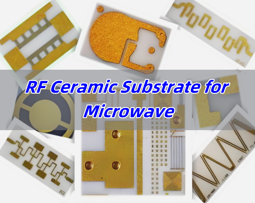
What is RF Ceramic Substrate?
RF ceramic substrate is a key component for RF circuit and microwave circuit, it refers to a specialized ceramic material designed to support high-frequency circuits used in radio frequency systems. Unlike traditional materials, ceramic substrates used for RF circuits offer low signal loss, stable dielectric properties, and strong thermal resistance. It is usually made of alumina (Al₂O) ₃ ceramic material, with good insulation properties, high temperature stability and low dielectric loss characteristics, the dielectric constant is usually between 9-12, dielectric loss Angle is less than 0.0003.
Types of RF Ceramic Substrate
1. Alumina-Based Substrate
Alumina (Al2O3) is widely used for RF ceramic substrates because it offers high thermal conductivity, good mechanical strength, and stable dielectric behavior at high frequencies. It can handle both RF and microwave signals, making it suitable for communication systems, radar, and aerospace devices.
2. Aluminum Nitride (AlN) Substrate
Aluminum nitride offers both high thermal conductivity and lower dielectric constant compared to alumina. This helps improve signal integrity in high-speed circuits. AlN substrates work well in applications needing both heat dissipation and frequency stability, like power amplifiers and phased array antennas.
3. Beryllium Oxide (BeO) Substrate
BeO substrates provide the highest thermal conductivity among ceramic options. Although used less frequently due to handling concerns, BeO still finds use in specialized high-power RF systems where heat removal is critical.
RF Ceramic Substrate vs. Normal Ceramic Substrate
Not all ceramic substrates perform equally, especially when handling RF signals. Regular ceramic substrates, like those used in standard circuits, mainly focus on mechanical strength and insulation. Electrical performance, especially at high frequencies, often comes second.
RF ceramic substrates, however, prioritize electrical performance. They offer low dielectric loss, controlled dielectric constant, and tight tolerances, all of which ensure signals move smoothly without distortion. In microwave circuits, even minor changes in material properties can cause signal loss or unwanted interference. In addition to this, they are differ from materials composition and applications:
1. Material Composition
- RF Ceramic Substrates: Typically made from Class I ceramic materials, including alumina (Al₂O₃), aluminum nitride (AlN), and silicon nitride (Si₃N₄). These materials offer good thermal conductivity, high-frequency performance, and excellent high-temperature stability.
- Normal Ceramic Substrates: Primarily made from inorganic materials like alumina (Al₂O₃) and aluminum nitride (AlN). While these materials perform well at high temperatures, they do not match RF ceramic substrates in terms of high-frequency performance.
2. Application Fields
- RF Ceramic Substrates: Primarily used in RF and microwave circuits, such as mobile communication base stations, broadcast transmitters, MRI coils, semiconductor RF power supplies, laser equipment, military radios, radar systems, and complete RF microwave devices. They are also used in power amplifiers, LC filters, transceiver modules, and microwave components.
- Normal Ceramic Substrates: Widely used in high-power LED lighting, high-frequency communication, and railway power systems. They are valued for their excellent heat dissipation and high-temperature stability.
Benefits of RF Ceramic Substrate for Microwave
1. Low Dielectric Loss
RF ceramic substrates minimize signal loss at high frequencies, which helps maintain signal strength even across longer transmission paths.
2. Stable Dielectric Properties
Ceramic substrates keep their dielectric constant stable across wide temperature and frequency ranges.
3. Excellent Thermal Management
Microwave circuits often generate heat, especially at higher power levels. Ceramic substrates, particularly AlN and BeO, offer strong heat dissipation, it helps prevent thermal damage while preserving electrical performance.
4. Environmental Durability
Microwave systems used in aerospace, defense, and satellite applications face harsh environments, including vibration, radiation, and extreme temperatures. Ceramic substrates handle these conditions without losing mechanical or electrical reliability.
5. Precision Manufacturing
Ceramic substrates for RF circuits support fine-line patterns, which allows designers to create high-density circuits without losing signal integrity.
Ceramic Substrate HS Code
The HS code for ceramic substrates used in electronic circuits generally falls under 8547.10.00. However, for substrates specifically designed for RF or microwave circuits, local customs authorities may apply slight variations depending on composition, thickness, or intended use.
Well-Known RF Ceramic Substrate Brands
When choosing RF ceramic substrates, selecting reliable materials from established brands helps ensure consistent performance. Several companies specialize in developing high-performance ceramic materials specifically for RF and microwave applications. Below are some well-known names trusted across industries like telecom, aerospace, automotive radar, and satellite systems.
- Rogers Corporation
- Kyocera Fine Ceramics
- Coorstek
- Murata Manufacturing
- Maruwa
- NGK Spark Plug Co., Ltd.
- Heraeus Electronics
At Best Technology, we offer customized RF ceramic PCBs for our customers, we have stable supply chain and enough stock in our warehouse. Therefore, we can handle time-sensitive orders and provide expedited service if you are urgent.
RF Ceramic Substrate Uses
- Wireless communication modules like 5G antennas, RF front-end modules, and satellite communication devices.
- Radar and sensing systems, including automotive radar, weather radar, and defense radar systems.
- Aerospace and space electronics, such as satellite payloads, deep-space communication, and onboard electronics.
- Medical imaging and equipment, including MRI and wireless telemetry devices.
- Industrial RF Systems, like RF heating systems, test instruments, and high-frequency sensors.
RF Ceramic PCB Design Considerations
Designing RF ceramic PCBs requires a deep understanding of both high-frequency circuit behavior and ceramic material properties. Compared to standard FR4 or other organic substrates, ceramic materials handle RF signals differently, especially at microwave and millimeter-wave frequencies. Below are the key considerations to achieve stable signal transmission, low loss, and reliable performance.
1. Dielectric Constant and Its Stability
The dielectric constant (Dk) directly affects signal propagation speed and impedance matching. Ceramic substrates, such as Al₂O₃ or AlN, typically have Dk values ranging from 9 to 10 for Al2O3 and 8 to 9 for AlN. It’s not just about Dk itself but also its stability over frequency and temperature changes. For RF circuits, materials with minimal Dk variation across frequencies (up to 40 GHz and beyond) help maintain consistent phase and impedance control, which directly impacts signal integrity.
2. Loss Tangent (Df) and Signal Attenuation
Loss tangent (Df) measures how much energy the substrate material absorbs during signal transmission. Lower Df leads to less signal attenuation, especially at high frequencies.
For comparison, FR4’s Df can exceed 0.015 at 10 GHz, While a reliable data from Murata’s ceramic materials shows Df values around 0.0005 to 0.0010 at 10 GHz, which outperforms many organic substrates.
3. Conductor Surface Roughness
For microwave circuits, copper foil roughness directly affects insertion loss. Rougher copper increases conductor loss, especially above 10 GHz. Ceramic PCBs often use low-profile copper, with surface roughness below 2 µm (Rz), to minimize skin effect losses at high frequencies.
4. Coefficient of Thermal Expansion (CTE) Matching
Alumina substrates typically have a CTE around 6.5 ppm/°C, which aligns reasonably well with copper’s 17 ppm/°C when using proper bonding techniques. For applications like satellite communications, where temperature swings can exceed ±100°C, this balance ensures mechanical reliability.
5. Transmission Line Structures and Impedance Control
To design RF circuits on ceramic substrates, engineers often use microstrip, coplanar waveguide (CPW), or stripline structures. Achieving tight impedance control (±5% or better) requires precise trace width calculation, gap spacing, and accurate Dk data across the operating frequency range. For example, a 50-ohm microstrip line on 99.6% alumina with a 0.635 mm (25 mil) thickness requires a trace width around 1.5 mm, but the exact value shifts slightly based on the operating frequency and whether the substrate uses thin-film or thick-film copper.
6. Thermal Management for High-Power RF Circuits
High-power RF circuits, such as power amplifiers (PAs) or radar transmitters, generate considerable heat. Aluminum nitride (AlN) substrates, with thermal conductivity reaching 170 W/m·K, outperform alumina (20-25 W/m·K) by almost seven times. This high thermal conductivity helps dissipate heat efficiently, reducing thermal gradients that could detune RF circuits.
7. Via and Plating Quality
Plated vias connect RF traces between layers or serve as ground vias to improve EMI shielding. In RF ceramic PCBs, via diameters as small as 100 µm are common, especially in LTCC packages.
For more information about RF ceramic PCB design guide, welcome to contact us at sales@bestpcbs.com. We offer free technical support for any PCB frequent asked questions.
Why Choose Best Technology as Your RF Ceramic PCB Supplier?
At Best Technology, we specialize in RF ceramic PCB manufacturing with over 18 years of experience serving global clients. We understand how critical dielectric stability, thermal management, and mechanical precision are for RF and microwave systems. Our in-house testing and quality checks ensure every board meets your performance standards, whether for 5G modules, radar systems, or aerospace electronics. At Best Technology, you can enjoy:
- Products control under ISO13485, IATF16949, AS9100D system
- Stable supply chain (cover various brands ceramic substrate)
- Cutting edge technology for ceramic PCB manufacturing
- Professional ceramic PCB engineer technical support
- DDU & DDP quotation
- 2-3Weeks delivery
- Highest quality
- Customized RF ceramic PCB design
- Turn-key service
With custom design support, quick turnaround, and flexible production options, we help clients bring RF innovations to market faster. Contact Best Technology today to see how our RF ceramic PCB solutions can support your next project.


