

Common PCB failures are mainly concentrated on components such as capacitors, resistors, inductors, diodes, transistors, MOSFETs, integrated chips (IC), and crystals. Some obvious damages can be visually detected, while others require the use of tools. Today, let’s learn how to troubleshoot PCB faults using a multimeter.
How Will You Diagnose a Faulty PCB By Visually?
For some printed circuit boards, we can check by our naked eyes. Here are some common ways to follow:
1. Check the condition of components
When you get a faulty PCB, first observe if there are any obvious component damages, such as burnt or swollen electrolytic capacitors, burnt resistors, and damaged power devices.
2. Inspect the soldering of the PCB
Check if the printed circuit board (PCB) is deformed or warped; if there are any loose or poorly soldered joints; if the copper cladding on the PCB is lifted, burnt, or blackened.
3. Examine the component plug-ins
Ensure the correct orientation of integrated circuits, diodes, and the PCB power transformer.
How to Check PCB with a Multimeter?
Before you start testing your PCB, ensure you have the right tools and environment. Here’s a checklist to get you started:
1. Safety First: Wear anti-static gloves and ensure you are working on an anti-static mat to prevent damage to the PCB.
2. Multimeter Selection: Choose a multimeter with the ability to measure voltage, resistance, and continuity. A digital multimeter is preferred for accuracy.
3. Visual Inspection: Examine the PCB for visible signs of damage such as burnt components, broken traces, or solder bridges.
4. Power Off the Board: Always test the PCB with the power off to avoid any electrical hazards and damage to the multimeter.
How Do You Test Individual Components on a PCB?
Testing individual components like resistors, capacitors, and diodes can pinpoint the exact failure. Here’s a general approach:
- Diode
- Transistor
- MOSFET
- Electrolytic Capacitors
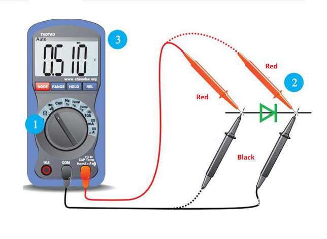
How to Test Diodes?
1. Set the MF47-type multimeter to measure resistance.
2. Place the red and black probes on the two ends of the diode and read the value.
3. Swap the probes and measure again.
4. Judge based on the two measurements: the forward resistance of small power germanium diodes is 300-500Ω, silicon diodes are about 1kΩ or larger. The reverse resistance of germanium diodes is tens of kilo-ohms, and silicon diodes are above 500kΩ (values are much smaller for high-power diodes). A good diode has low forward resistance and high reverse resistance, and the larger the difference, the better.
5. If both forward and reverse resistances are very low, the diode is short-circuited; if both are very high or infinite, the diode is open-circuited and needs to be discarded.
How to Test Transistors?
1. Set the digital multimeter to the diode mode.
2. Measure the PN junction with the probes. If it conducts forward, the displayed value is the forward voltage drop of the PN junction.
3. Determine the collector and emitter: measure the forward voltage drop of the two PN junctions, the larger drop is the emitter (e), and the smaller drop is the collector (c). If the red probe is connected to the common terminal, the transistor is NPN type, and the common terminal is the base (b); if the black probe is connected to the common terminal, the transistor is PNP type, and the common terminal is the base (b).
4. For in-circuit testing, measure the forward and reverse resistance of the PN junction to determine if the transistor is damaged. If the branch resistance is larger than the forward resistance of the PN junction, there should be a clear difference between the forward and reverse resistances, otherwise, the PN junction is damaged.
The Way to Test MOSFETs?
1. Connect the black probe to the drain (D) and the red probe to the source (S), the resistance should be 500-600.
2. Without moving the black probe, touch the gate (G) with the red probe, then measure the source (S) again; it should conduct.
3. Connect the red probe to the drain (D), touch the gate (G) with the black probe, then measure the source (S); the resistance should be the same as the first measurement, indicating the MOSFET is working normally.
How to Test Electrolytic Capacitors?
1. Select the appropriate range on the MF47-type multimeter based on the capacitor’s capacity. Use R×1K range for capacitors below 47μF, and R×100 range for those above 47μF.
2. Connect the red probe to the negative lead and the black probe to the positive lead of the capacitor.
3. On initial contact, the multimeter needle will deflect right and then gradually return to the left until it stops at a certain position (close to infinity). This value is the capacitor’s forward leakage resistance; the larger the value, the better the capacitor’s performance.
4. Swap the probes and repeat the process. The measured value will be the reverse leakage resistance, slightly smaller than the forward leakage resistance.
5. If no charging phenomenon occurs (the needle doesn’t move), the capacitor is either open or short-circuited internally. If the resistance is very small or zero, the capacitor is leaky or has broken down and cannot be used.
This is the end of this article, if you want to know more about it, welcome to contact us.