What is the SMT?
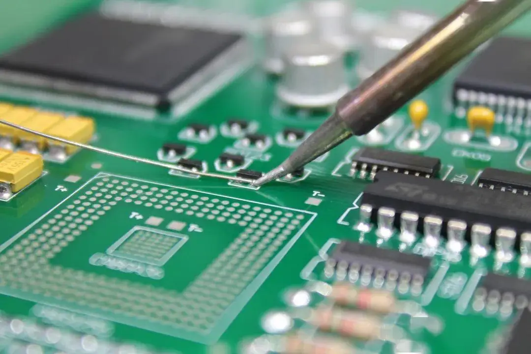
Surface Mount Technology (SMT) is a production technique used to attach electronic components directly onto the surface of a printed circuit board (PCB). This method enables automated manufacturing to handle most of the assembly process needed to create a functioning board. Components attached in this way are known as surface-mount devices (SMDs). Unlike traditional methods, SMT does not involve inserting components through holes in the board. Instead, components are soldered directly onto the surface using reflow soldering.
Originally known as Planar Mounting, SMT was pioneered by IBM in the 1960s for small-scale computer production, replacing the earlier Through-Hole Technology. However, SMT didn’t gain widespread use until 1986, when surface-mounted components achieved 10% market penetration. By 1990, SMDs had become a dominant feature in most high-tech circuit card assemblies (CCAs).

What is the process of SMT manufacturing?
The SMT manufacturing process can be divided into three main stages: solder paste printing, component placement, and reflow soldering. Due to the complexity of the process, each stage is further broken down as follows:
1. Component and PCB Preparation
This initial stage involves selecting surface-mount components (SMCs) and designing the PCB. The board typically features flat copper pads plated with silver, tin-lead, or gold, which are called solder pads. These pads do not have holes and are used to support the pins of components like chips and transistors.
Another crucial element is the stencil, which is aligned with the solder pads to define the placement of solder paste during the next stage. The PCB and all materials involved must be thoroughly inspected to ensure there are no defects before proceeding with production.
2. Solder Paste Printing
Solder paste printing is a critical phase in SMT production. A stencil and squeegee are used to apply solder paste at an angle of 45° to 60°. The solder paste itself is a combination of powdered metal solder and flux, which temporarily holds components in place and cleans the soldering surfaces of impurities.
The paste is applied to the solder pads, connecting the SMCs to the PCB once melted in the reflow oven. It’s essential that the correct amount of paste is applied to each pad, as improper application can prevent proper connections from forming during reflow.
3. Component Placement
In this stage, pick-and-place machines accurately position components on the PCB. The machines use vacuum or gripper nozzles to remove each component from its packaging and place it onto the board. These machines are fast and precise, capable of placing up to 80,000 components per hour.
Precision is key here, as any misplaced components could lead to costly rework once soldered.
4. Reflow Soldering
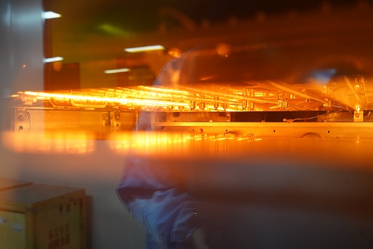
After components are placed, the PCB is moved into the reflow oven for soldering. The board passes through several temperature-controlled zones:
- Preheat Zone
The temperature is gradually increased to between 140℃ and 160℃ at a rate of 1.0℃-2.0℃ per second to ensure the board and components heat evenly.
- Soak Zone
The PCB is maintained at this temperature for 60 to 90 seconds to stabilize the heat across the entire board.
- Reflow Zone
The temperature is then raised to 210℃-230℃ to melt the solder paste, bonding the components to the PCB. The molten solder’s surface tension keeps the components in place during this process.
- Cooling Zone
In the final zone, the solder is rapidly cooled to solidify the connections and prevent any soldering defects.
For double-sided boards, this process may need to be repeated, either using solder paste or adhesive to secure components.
5. Cleaning and Inspection
Once the soldering process is complete, the PCB is cleaned and inspected for any defects. This is done using magnifying lenses, Automated Optical Inspection (AOI), flying probe testers, X-ray inspection, and other tools to ensure accuracy. Any flaws are repaired before the finished product is packaged and stored.
What are the basics of SMT?
SMT simplifies assembly by reducing the need for drilled holes and using smaller components. Unlike traditional through-hole components, SMT parts are placed on the surface of the PCB, making the design more compact.
The basic elements of SMT include:
- PCBs: The base for components, designed with specific pads for each part.
- Solder Paste: A mixture of metal solder particles and flux, used to create a bond between components and the board.
- SMT Components: Small electronic parts, such as resistors, capacitors, and ICs, that attach to the PCB.
The transition from through-hole technology to SMT has improved manufacturing speed and performance in electronics.
How do I prepare for SMT?
As the core step of electronic product manufacturing, PCBA’s preparation before assembly directly affects the quality and reliability of the final product. The following is a detailed analysis from multiple dimensions:
1. Component inspection
Before assembly, all electronic components must undergo strict screening and inspection. This includes checking that the component type, package, number of pins, etc. are consistent with the BOM (Bill of Materials), as well as performing the necessary electrical performance tests.
2. Take ESD measures
Static damage to electronic components is invisible, but the consequences are serious. Therefore, when distributing materials and testing IQC, warehouse personnel should wear anti-static gloves, reliably ground the instrument, and lay anti-static rubber MATS on the work surface. During the assembly process, the operator should also wear anti-static clothes, anti-static bracelets and other protective equipment to ensure that the workbench and equipment are well grounded.
3. Cleanliness requirements
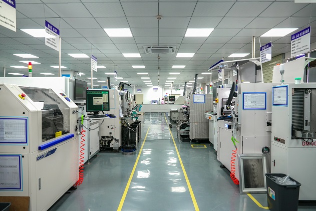
The work workshop and workbench must be kept clean to prevent contaminants such as dust and impurities from entering the circuit board, affecting the accuracy and quality of the patch. Clean the work surface and workshop floor regularly. Smoking, eating and drinking are strictly prohibited in the work area.
4. Temperature and humidity control
Appropriate temperature and humidity should be maintained in the workshop to reduce static electricity generation and the impact on electronic components. It is usually recommended that the temperature be controlled at 23±3oC and the humidity be controlled at 45% to 70%RH. This environment helps to ensure the quality of welding and the stability of electronic components.
5. PCB appearance check
Before assembly, the PCB board should be visually inspected to confirm whether it is complete, whether the surface coated solder resistance layer is intact, and whether there are obvious short circuits and defects. Use a multimeter to check whether there is a short circuit between the power supply and the ground terminal on the printed board, and ensure that the printed board is fine.
6. Check the software and hardware
When the PCBA needs to be upgraded, the motherboards produced in different time periods should not be mixed together to avoid mixing problems. Before assembly, check whether the final use of the software is in accordance with customer requirements to ensure that the software and hardware are compatible and correct.
7. Welding process selection
According to the layout of the circuit board and the characteristics of the components, select the appropriate welding process (such as wave soldering, reflow welding, hot blast furnace welding, etc.). Each welding method has specific requirements for the placement, orientation and spacing of components that need to be planned in advance.
8. Manually prepare the post-welding plug-in components
For some components that cannot be automatically welded (such as large connectors, heat sinks, etc.), manual plug-in assembly is required. This requires the operator to have a wealth of experience and skilled skills to ensure the accuracy and robustness of the plug-in.
9. Perform ESD operations
During operation, use an ESD workbench and an ESD container to hold components and semi-finished products. All welding equipment should be grounded, the electric soldering iron must be anti-static type, and tested before use.
10 Cleaning and protective treatment
After the assembly is complete, the product needs to be cleaned to remove the residue and contaminants generated during the welding process. At the same time, appropriate protective treatment of the product, such as spraying three anti-paint, etc., to improve the product’s moisture, dust and corrosion resistance.
Which solder paste is used in SMT?
The type of solder paste used in SMT assembly process depends on several factors, such as the materials of the components and the PCB, as well as the operating conditions of the finished product. Generally, there are mainly include high temperature solder paste, medium temperature solder paste and low temperature solder paste.
- High temperature solder pastes are commonly used in applications where higher temperatures are required for welding. has a higher melting point and is suitable for welding electronic components with specific temperature requirements.
- Medium temperature solder paste and low temperature solder paste are suitable for medium and low temperature welding respectively, select the appropriate solder paste type according to the specific welding needs.
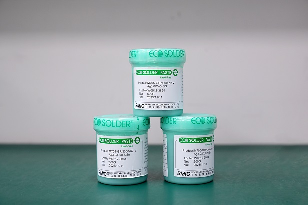
In addition, solder paste can also be classified according to the flux activity level, including “R” ( inactive) , “RMA” class ( moderate activity) , “RA” class ( completely reactive) and “SRA” class ( super activity). Different types of activity levels are suitable for different application scenarios, for example, “R” grade is usually used for welding aerospace, avionics products, and “RA” grade is suitable for consumer electronics products. This classification allows users to choose the right solder paste according to the specific application needs and cleaning process requirements.
What temperature should a soldering iron be for SMT?
The right temperature for soldering in SMT can vary depending on the solder paste and components you’re using. Typically, the soldering iron should be set between 250°C and 300°C. Using a lower temperature might not properly melt the solder, while a higher temperature could damage components or the PCB.
Of course, different types of PCB requires different temperature. For example, ceramic PCBs has fragile surface, so a lower temperature is good.
What are the disadvantages of SMT?
- Small volume (due to the limitation of components)
- Fragility
- High soldering requirements
- Easily damaged or dropped
- Challenging to inspect
- Complex process and inspection
- High equipment investment
How to solder SMT at home?
Soldering SMT components at home can be tricky, but with the right tools and techniques, it’s doable. Here’s a quick guide:
- Tools: You’ll need a fine-tip soldering iron, tweezers, solder paste, and flux. You may also want a magnifying glass or microscope for better visibility.
- Apply Solder Paste: Use a small amount of solder paste on the pads of the PCB where you want to place your components.
- Place Components: With tweezers, carefully place the components onto the solder paste. Make sure they are properly aligned with the pads.
- Reflow the Solder: If you have a reflow oven, you can use it to heat the board. Alternatively, a hot air rework station can also work.
- Inspect: Once the solder has cooled, check the connections. If necessary, reheat or add more solder to fix any weak joints.
Best Technology is a one-stop PCB & PCB assembly manufacturer founded in 2006, with 5 assembly lines. If you have needs for PCB and PCBA fabrication, we can be your reliable supplier from prototypes to bulk production. In addition, we have SMT factory in Vietnam, if you don’t want to make smt in Shenzhen, then we can support you in Vietnam. Welcome to contact us if you have such PCB and PCBA projects.
Tags: PCBA, SMT, smt process


