
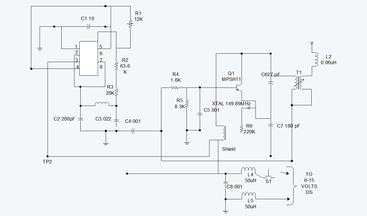
A circuit diagrams, also known as an electrical diagram, schematic diagram, or electronic schematic diagram, is a graphical representation of a simplified circuit. It is a visual tool for the design, construction, and maintenance of electrical and electronic equipment.
By utilizing images or standard symbols of different components, circuit diagrams can simplify the description of the components of a circuit and their interconnections. This enables electricians and technicians to easily understand the relative positions of components and their relationships in the circuit.
How to learn circuit diagram easily?
1. Knowing electrical components: First, you need to understand common electrical components, such as AC contactors, push button switches, thermal relays, time relays, etc., and master their working principles and structures.
2. Memorizing electrical symbols: Learn and memorize common electrical letters and graphic symbols, such as AC contactors (KM), intermediate relays (KA), etc.
3. Basic theory learning: Have basic electrical basic knowledge, such as the relationship between the rotation direction of a three-phase asynchronous motor and the phase sequence of the power supply.
4. Practical operation: If conditions permit, disassemble electrical components to familiarize yourself with their internal structure, or understand the internal structure and working principle through physical diagrams.
5. Practice step by step: Start with simple circuit diagrams and gradually try to analyze more complex circuit diagrams. Through continuous practice, you can gradually improve your ability to interpret circuit diagrams.
6. Use the principle of circuit simplification: Learn and apply the basic principles of circuit simplification, such as ignoring wire resistance, switch processing, etc.
7. Combine theory with practice: Apply theoretical knowledge to practice, for example, try to design your own circuit based on the learned electrical schematics, or design circuit diagrams according to actual needs.
Through the above steps and methods, you can learn and understand circuit diagrams more easily.
What are the 4 rules for drawing circuit diagrams?
The 4 rules for drawing circuit diagrams are:
1. Circuits or components should be arranged according to function and arranged in working order as much as possible.
2. All electrical components should be represented by graphic symbols and text symbols that are unified by national standards.
3. Different parts of the same electrical component (such as coils and their multiple contacts) are often not drawn together, but should be marked with the same text symbol.
4. In the circuit schematic, all contacts of the control appliance should be drawn in the “non-excitation” state.
These rules together ensure that the circuit diagram is clear, accurate and easy to understand, and provide an important reference for the design and maintenance of electronic equipment and systems.
How to get better at reading schematics?
Understand the basic composition and logic block diagram of the circuit: First, you need to understand the relationship between the various components in the schematic, such as power supply, reset, etc., and the connection relationship between the various devices on the motherboard.
Pay attention to details: When reading the schematic, you need to pay attention to details, such as the model of the components, the connection method, etc.
Do more exercises: Through a lot of reading and practice, you can become familiar with various circuit types and topics and gain more knowledge and experience from them.
Use relevant knowledge of analog circuits and circuit design: Having a deep understanding of the basic concepts and principles of analog circuits and circuit design can help better understand how the various parts in the schematic work together.
What are the components of common circuit schematics?
Power supply: The power supply provides electrical energy to the circuit in the form of voltage and current. Every functional electronic circuit requires a DC or AC power supply.

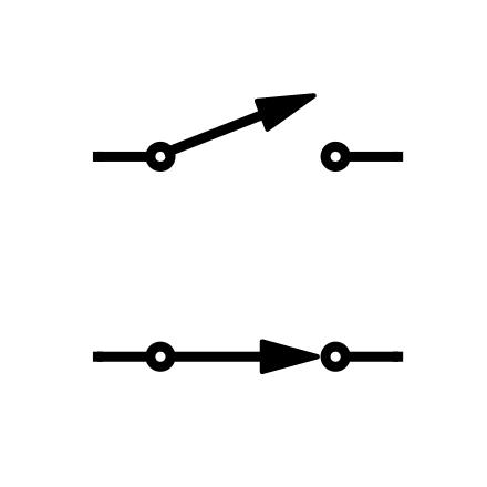
Switches: Switches can make or break connections in a circuit. They can also change the path that current flows.
Capacitors: Capacitors are passive electronic components that store electrical charge. There are two common types of capacitors: nonpolar capacitors and polar capacitors.
Diodes: A diode is a polarized device that allows current to flow in only one direction. Because it is polarized, it has a positive terminal (anode) and a negative terminal (cathode). The flat side of the triangle is the anode, and the line is the cathode.

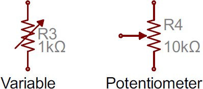
Potentiometers and variable resistors: Both variable resistors and potentiometers have an arrow added to the standard resistor symbol. Variable resistors are still two-terminal devices, so the arrow just goes diagonally through the middle. Potentiometers are three-terminal devices, so the arrow becomes the third terminal (the wiper).
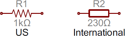
Resistors: The most basic circuit component and symbol, resistors on schematics are usually represented by a few jagged lines with two terminals extending outward. Schematics using international symbols may use a featureless rectangle instead of a wavy line.
What does a resistor do in a circuit?
Resistance (usually represented by “R”) is a physical quantity that indicates the magnitude of the resistance of a conductor to the current in physics.
The greater the resistance of a conductor, the greater the resistance of the conductor to the current. Different conductors generally have different resistances, which is a characteristic of the conductor itself. Moreover, the main functions of resistors in circuits include current shunting, current limiting, voltage division, biasing, filtering (used in combination with capacitors), impedance matching, and converting electrical energy into internal energy.
What is the simplest of all circuit diagrams?
The simplest of all circuit diagrams is the series circuit.
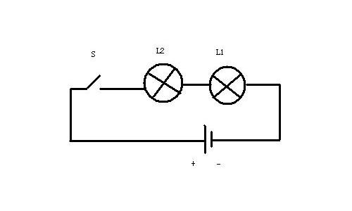
The series circuit is one of the most basic circuit connection methods, consisting of components such as power supply, wires, switches, and electrical appliances. The characteristic of this circuit is that the path of current passing through each component is single, that is, the current flows out from the positive pole of the power supply, passes through each component and reaches the negative pole of the power supply.
The structure of the series circuit is simple and easy to understand and construct. Therefore, the series circuit is an important concept in the basic stage of circuit learning. In addition, the single path nature of the series circuit makes it the basis for understanding and analyzing complex circuits, laying the foundation for subsequent learning of more complex circuit structures such as parallel circuits and hybrid circuits.
Conclusion:
Circuit diagrams are an important tool in the field of electronics that provide a visual representation of circuits. These diagrams are essential for designing, troubleshooting, and understanding how electronic components are interconnected.
Whether you are a beginner or an experienced engineer, mastering the skill of reading circuit diagrams is the foundation for a successful career in electronics. It enables you to effectively design, troubleshoot, and understand electronic circuits. You can master this important skill by becoming familiar with common symbols, understanding circuit layouts, and practicing regularly.
You may also like


Tags: circuit, circuit diagrams