A power supply circuit is at the heart of every electronic device, transforming available energy into usable power. Whether you’re developing a new product or repairing an existing one, a firm grasp of power supply circuit design helps in improving efficiency, and performance. The main objective of this blog is to share know-how about power supply circuit, from the definition, types, power supply circuit board and more. Here we go!
What Are the Three Types of Power Supply?
There are three subsets of regulated power supplies: linear, switched, and uninterruptible battery based. Of the three basic regulated power supply designs, linear is the least complicated system, but switched and battery power have their advantages.
Linear power supply
This is one of the simplest forms. It uses a transformer to reduce the input voltage to the desired level, then relies on a regulator to maintain stable voltage. Linear power supplies are known for their low noise output and reliability. However, they can be inefficient because they dissipate excess energy as heat.
Switching power supply
This type is much more efficient than linear power supplies. It rapidly switches the power on and off to control the output voltage. By doing so, switching power supplies can achieve higher efficiencies, making them ideal for modern electronics where energy conservation is crucial. They are compact and offer better energy savings but can introduce noise into the circuit.
Uninterruptible power supply (UPS)
A UPS provides emergency power when the main source fails. It’s widely used in environments where power interruptions could cause data loss or equipment damage, such as in data centers or hospitals. It combines elements of both linear and switching power supplies, offering reliability and backup in case of failure.
What Are the Problems with Power Supply Circuits?
Power supply circuits are not without challenges, but understanding these issues can help mitigate them.
- Heat generation
Some power supplies, especially linear ones, generate significant heat during operation. This can affect the longevity of components and the overall performance of the device. Adding heat sinks or better cooling can help manage this issue.
- Voltage fluctuations
Inconsistent power supply can lead to voltage drops or spikes. Sensitive electronics might malfunction or get damaged under such conditions. Proper filtering and regulation can address these fluctuations.
- Electrical noise
Switch-mode power supplies are efficient but can introduce electrical noise into the circuit. This noise can interfere with the performance of other components, especially in sensitive applications. Careful circuit design, shielding, and grounding can reduce the impact.
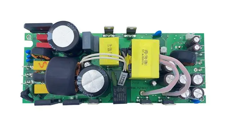
Common Power Supply Circuit Diagram
A diagram representing circuit connections with circuit component symbols is called a circuit diagram. Circuit diagram is a kind of schematic layout diagram that represents the composition and relationship of components and devices drawn by the symbols of physical and electrical standardization for the needs of research and engineering planning, which can know the working principle of components and provide planning schemes for the analysis of performance and installation of electronic and electrical products.
Circuit diagram is one of the basic skills that electronic engineers must learn, here we listing four common power supply circuit diagrams, which is super full super detailed. Hope it is useful for you!
Regulated Power Supply Circuit Diagram
This type uses voltage regulators to maintain a constant output voltage regardless of input fluctuations. Let’s take an example of an 3~25V adjustable voltage regulator circuit. This regulated power supply can be adjusted within a range of 3.5V to 25V. It provides a large output current and uses an adjustable voltage regulator circuit. You can see its circuit diagram as below:
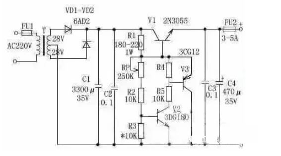
Its working principle is: after rectification and filtering, the DC voltage is supplied to the base of the adjustment transistor through R1, which makes the transistor conduct. When V1 conducts, the voltage passes through RP and R2 to make V2 conduct, and then V3 also conducts. At this point, the emitter and collector voltages of V1, V2, and V3 no longer change (their function is completely similar to that of a zener diode). By adjusting RP, a stable output voltage can be obtained. The ratio of R1, RP, R2, and R3 determines the output voltage of this circuit.
Component Selection
Transformer T: Choose an 80W to 100W transformer, with an input of AC220V and a dual winding output of AC28V.
FU1: Use a 1A fuse.
FU2: Use a 3A to 5A fuse.
VD1, VD2: Use 6A02 diodes.
RP: Use an ordinary potentiometer rated at around 1W, with a resistance value between 250K and 330K.
C1: Use a 3300µF/35V electrolytic capacitor.
C2, C3: Use 0.1µF monolithic capacitors.
C4: Use a 470µF/35V electrolytic capacitor.
R1: Use a resistor with a value between 180Ω and 220Ω, rated at 0.1W to 1W.
R2, R4, R5: Use 10KΩ resistors, rated at 1/8W.
V1: Use a 2N3055 transistor.
V2: Use a 3DG180 or 2SC3953 transistor.
V3: Use a 3CG12 or 3CG80 transistor.
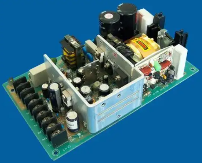
Switched-Mode Power Supply (SMPS) Circuit
This circuit is used in many modern electronics because of its high efficiency. It includes a switching regulator that controls the energy flow, converting the input voltage to the required output through rapid switching. Below is a power supply circuit diagram of a 12V, 20W SMPS system with TOP224P.
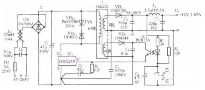
From the above, VDz1 and VD1 clamp the spike voltage generated by leakage inductance to a safe level and attenuate ringing voltage. VDz1 uses a P6KE200 transient voltage suppressor with a reverse breakdown voltage of 200V, while VD1 is a UF4005 ultra-fast recovery diode rated at 1A/600V. The secondary winding voltage is rectified and filtered through VD1, C2, L1, and C3, producing a 12V output voltage (Uo). The value of Uo is determined by the sum of the stable voltage of VDz2, the forward voltage drop across the LED in the optocoupler, and the voltage drop across R1.
By adjusting the turns ratio of the high-frequency transformer and the stabilization value of VDz2, other output voltages can also be obtained. R2 and VDz2 provide a dummy load for the 12V output, improving load regulation during light load conditions. The feedback winding voltage is rectified and filtered by VD3 and C4 to supply the necessary bias to the TOP224P. Common mode choke L2 reduces common-mode leakage current caused by the high-voltage switching waveform on the primary winding’s D-terminal. C7 filters interference from the coupling capacitance between the primary and secondary windings, while C6 minimizes differential-mode leakage currents from the primary winding. Additionally, C5 filters peak current on the control terminal and, together with R1 and R3, compensates the control loop and determines the self-starting frequency.
Transformer-Based Power Supply Circuit
This is the most basic power supply circuit, often used in low-power applications. It involves a transformer to reduce the input AC voltage, followed by rectification and filtering to produce a steady DC output.
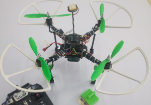
Battery-Powered Circuit
For portable devices, battery-powered circuits offer a reliable power source. These circuits are designed to manage the charging and discharging of batteries while providing stable power to the device.
Which kind of PCB used for power supply circuit?
1. Heavy copper PCB
Heavy copper PCBs are designed with significantly thicker copper layers compared to standard PCBs. Typically, they feature copper weights greater than 3 ounces per square foot. These PCBs excel in handling higher currents and distributing power across the circuit more effectively, making them ideal for power distribution systems, power converters, and other demanding applications. Bus bar PCBs are a subtype of heavy copper boards, specifically designed for applications requiring high current capacity and low impedance.
Heavy copper PCBs are used when standard copper traces cannot carry the required current without excessive heat buildup. By increasing the thickness of the copper layers, these PCBs can manage higher currents, dissipate heat better, and enhance the board’s durability. They are crucial in industries like automotive, solar power, and industrial control, where reliable power management is key.
2. Metal Core PCB
Metal core PCBs also call led pcb board, are built with a metal substrate, typically aluminum or copper, to efficiently dissipate heat generated by high-power circuits. These boards are widely used in LED lighting, power supplies, and automotive electronics where heat management is essential. For extra high power supply applications, copper core PCB is a good choice.
3. Ceramic PCB
Ceramic PCBs are highly favored in environments where high thermal conductivity and electrical insulation are needed. They can be used under -80C ~ 2200C. They perform well in high-frequency applications and can operate in harsh conditions, making them suitable for aerospace, military, and industrial power electronics.
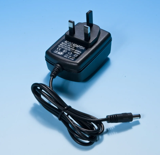
How to Build a 12V Power Supply Circuit?
Building a 12V power supply circuit can be a rewarding project, whether you’re creating it for a specific device or learning about electronics. Below is a detailed guide to help you design and build a reliable 12V power supply.
Components Needed
Before you begin, gather the essential components:
- Transformer: A step-down transformer will reduce the AC mains voltage (usually 110V or 220V) to a lower AC voltage that can be rectified and regulated to 12V DC. A common choice is a transformer that outputs 15V AC.
- Bridge Rectifier: This consists of four diodes arranged to convert AC to DC. The diodes ensure that the output is always in the same polarity, transforming the alternating current into a pulsating direct current.
- Capacitors: Capacitors act as filters to smooth out the pulsating DC output from the rectifier, reducing ripple and providing a more stable DC voltage.
- 12V Voltage Regulator: A voltage regulator like the LM7812 ensures that the output remains at a steady 12V DC. This is crucial to prevent voltage fluctuations, which could damage sensitive electronic components.
- Heat Sink: A heat sink is necessary to dissipate heat from the voltage regulator, especially when there’s a significant voltage drop between the input and the 12V output.
- Fuse: To protect your circuit from overcurrent situations, a fuse should be added at the input or output stage.
- Optional Components: You might include an LED indicator and resistor to show when the power supply is active.
Step-by-Step Process
Here’s how to assemble the components into a functional 12V power supply circuit:
Step 1: Connect the Transformer
The transformer’s primary winding is connected to the AC mains, reducing the input voltage to around 15V AC on the secondary winding. This step-down AC voltage will feed into the rectifier circuit.
Step 2: Bridge Rectifier Configuration
The output of the transformer is connected to the bridge rectifier. The rectifier converts the AC voltage into a pulsating DC voltage. The output voltage will still have ripples (fluctuations in the voltage level) and needs further smoothing.
Step 3: Filter the Output with Capacitors
A capacitor is connected across the output of the bridge rectifier to smooth the pulsating DC signal. This helps to reduce ripple and stabilize the voltage. A larger capacitor will give better smoothing, but a typical value used is around 1000µF. The capacitor works by charging up during the peaks of the rectified signal and releasing energy during the valleys, leading to a more stable DC voltage.
Step 4: Voltage Regulation
After the rectified and filtered voltage, you will likely have a DC voltage around 15V, which is still too high for a 12V power supply. This is where the 12V voltage regulator (e.g., LM7812) comes into play. The regulator ensures the output remains at a constant 12V, regardless of input variations or load changes.
1. Connect the input pin of the regulator to the positive output of the rectifier.
2. Connect the ground pin to the common ground.
3. The output pin will now deliver a regulated 12V DC.
Step 5: Add the Heat Sink
Voltage regulators can generate significant heat, especially when the difference between the input and output voltage is large. Attach a heat sink to the regulator to prevent overheating and ensure stable operation.
Step 6: Safety Measures
To protect the circuit from potential damage, include a fuse on the input side. This fuse will blow if there’s a short circuit or an overload, preventing the transformer or other components from getting damaged. For example, you can use a 1A fuse.
Step 7: Test the Circuit
Once the circuit is assembled, double-check all connections and test the output with a multimeter. Make sure the output voltage is stable at 12V under no load and when powering a device.
Optional: Add Features
You can add an LED indicator with a series resistor to the output side. This will visually indicate when the power supply is on and functioning.
Practical Considerations
Load Capacity: The transformer’s power rating (VA) should be sufficient to handle the current drawn by the load. For instance, if your load requires 1A at 12V, the transformer must be able to supply at least 12 watts (plus some margin to account for inefficiency and losses).
Heat Management: If your power supply will be operating under heavy load, consider adding active cooling, such as a small fan, especially if the heat sink alone does not adequately dissipate heat.
Enclosure: For safety and aesthetics, house the power supply in an insulated, vented enclosure to prevent accidental contact with live wires and to allow for heat dissipation.
A Simple Example
Once completed, this 12V power supply circuit can be used for a wide variety of applications:
Small Electronics Projects: Power up microcontrollers, sensors, or other small electronics that run on 12V.
LED Lighting: It can be used to power 12V LED strips or other lighting systems.
Arduino or Raspberry Pi Projects: Many DIY electronics projects require a steady 12V supply to operate correctly, and this circuit can deliver that power reliably.