


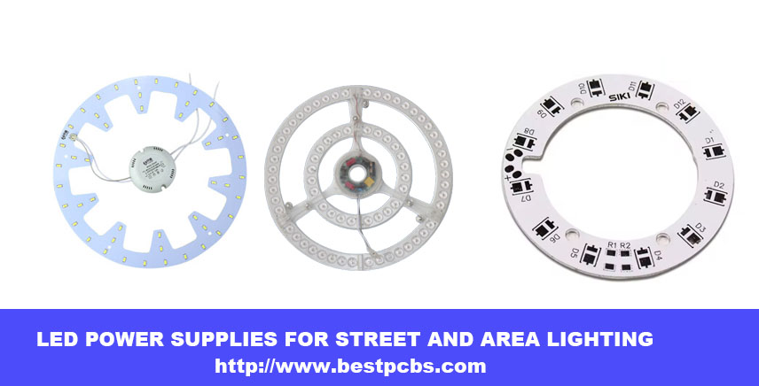
led ring light pcb leads the development of lighting industry with its innovative design, high efficiency and flexibility, bringing more intelligent and comfortable lighting experience to our life.
It is not only an integrated platform of electronic components, but also a perfect combination of modern technology and aesthetics, and is the focus of future lighting trends.
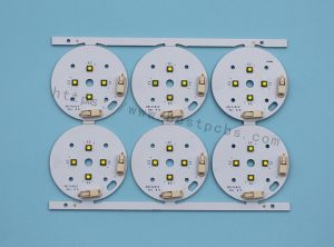
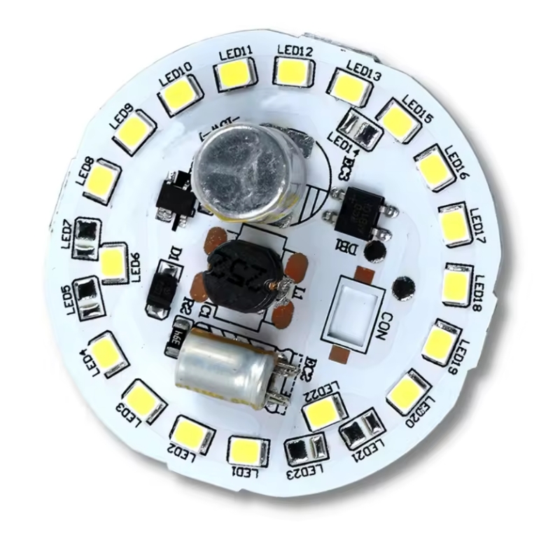
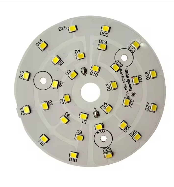
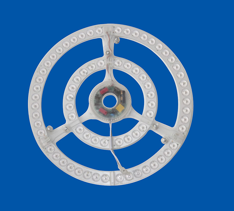
led ring light pcb, like a magic wand on the electronic stage, uses precise SMT technology to lightly attach LED components to it. Whether it is a warm small lamp for home decoration, efficient lighting in commercial space, or smart display inside the car, it is indispensable.
Its core structure includes efficient LED lamp beads, power cords that provide electricity, and intelligent controllers that adjust light effects, which together build an excellent lighting solution.
What Is led ring light pcb
Why use mcpcb for led ring light pcb
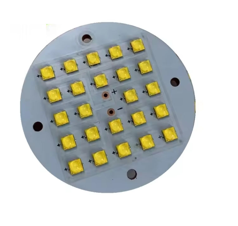
With the continuous development of LED technology, the heat generated by LEDs has gradually increased. The traditional FR4 printed circuit board (PCB) has been unable to meet the heat dissipation requirements due to its low thermal conductivity (only 0.36W/m.K). In order to solve this problem, the metal core printed circuit board (MCPCB) was proposed. It attaches the original printed circuit board to a metal with better thermal conductivity (such as aluminum and copper) to enhance the heat dissipation effect. The thermal conductivity efficiency of MCPCB is higher than that of traditional FR4 PCB, reaching 1W/m.K to 2.2W/m.K, which effectively improves the heat dissipation performance of LED PCB.
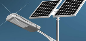
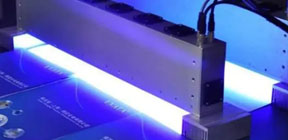
In addition, the use of MCPCB can also reduce the number of LEDs required to generate lighting, making it an ideal choice for street lights, automotive LED applications, and backlight unit applications. The use of metal substrates has practical advantages in heat dissipation, thermal conductivity, reliability, and electrical insulation, especially in harsh environments, and can also achieve reliable operation of LEDs. For example, using a metal substrate can reduce the LED junction temperature by 20-30°C, improve light output and enhance the overall performance of the product, ensure consistent UV light generation, and expand the possibilities of UV applications in various industries.
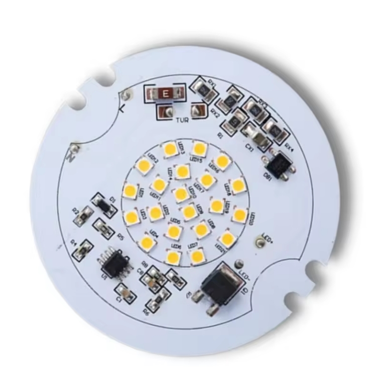
Unveiling the Components of LED PCBs
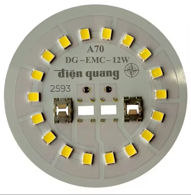
- LED Chips: The heart of the LED PCB, these semiconductor chips emit light when current passes through them.
- Substrate Material: The base layer of the PCB provides mechanical support and thermal conductivity.
- Copper Traces: These conductive pathways connect the LEDs and other components, allowing current to flow through the circuit.
- Solder Mask: A protective layer that covers the copper traces, safeguarding them from external factors and preventing short circuits.
- Silkscreen: This layer contains markings and labels, providing important information about the PCB’s components and assembly.
Advantages of led ring light pcb?
Thermal performance advantages of metal substrate PCB
High thermal conductivity:
The thermal conductivity of metal substrate PCB is much better than that of traditional plastic substrates such as FR4. It can effectively conduct the heat generated by components, reduce the operating temperature of components, and improve the reliability and life of circuit boards.
Good thermal stability:
Metal substrate PCB can maintain good dimensional stability and electrical performance in high temperature environment, and is suitable for high temperature working environment.
Mechanical performance advantages of metal substrate PCB
High strength: Metal substrate PCB has high mechanical strength and rigidity, is not easy to deform and break, and can withstand large external forces and vibrations.
Good processability: Metal substrate PCB can be processed by conventional mechanical processing methods such as drilling and cutting, which is convenient for the production of circuit boards with complex shapes and sizes.
Electrical performance advantages of metal substrate PCB
Excellent electrical insulation performance: Metal substrate PCB has a special insulation layer design to ensure good electrical insulation performance and avoid electrical short circuits between components.
Low impedance: The conductive layer of metal substrate PCB is made of metal material, which has low impedance, which is conducive to signal transmission and processing.
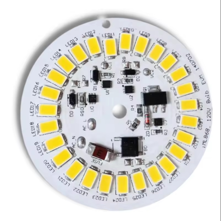
How does led ring light pcb dissipate heat?
The power device is mounted on the circuit layer. The heat generated by the device during operation is quickly transferred to the metal base layer through the insulating layer, and then the metal base layer transfers the heat to achieve heat dissipation of the device.
Compared with the traditional FR-4, the aluminum substrate can reduce the thermal resistance to the minimum, making the aluminum substrate have excellent thermal conductivity; compared with the thick film ceramic circuit, its mechanical properties are extremely good.
In the circuit design scheme, the heat diffusion is handled very effectively, thereby reducing the module operating temperature, extending the service life, and improving the power density and reliability; reducing the assembly of the heat sink and other hardware (including thermal interface materials), reducing the product volume, and reducing the hardware and assembly costs; combining the power circuit and the control circuit
How to make a LED light circuit board?
Step 1: Design Your LED PCB:
Using PCB design software, create a schematic for your LED circuit and design the PCB layout, considering component placement and signal flow.
Step 2: Choose the Materials:
Select a suitable substrate material and copper-clad board based on your project requirements.
Step 3: Transfer the Design:
Print your PCB layout onto a special transfer paper and transfer it onto the copper-clad board using a heat press.
Step 4: Etch the Board:
Immerse the board in an etching solution to remove the excess copper and reveal the copper traces.
Step 5: Drill Holes:
Drill holes on the board to accommodate the LED chips and other components.
Step 6: Solder the Components:
Carefully solder the LED chips and other components onto the board, ensuring secure connections.
Step 7: Test Your LED PCB:
Connect your LED PCB to a power source and test the LEDs to ensure they light up correctly.
How to make a LED light circuit board?
Capabilities of led ring light pcb?
| Item | Capabilities |
| Layer Count | 1 – 10 Layers |
| Max Board Dimension | 24*64″(610*1625mm) |
| Min Board Thickness | 0.6mm |
| Max Board Thickness | 4.0mm |
| Conductor Thickness | 0.5oz – 10oz |
| Min Line Width/Line Space | 4/4mil (0.10/0.10mm) |
| Min Hole Diameter | 10mil (0.25mm) |
| Min Punch Hole Dia | 0.12″ (3.0mm) |
| Min Hole Spacing | 16mil (0.4mm) |
| Min PAD Ring(Single) | 3mil (0.075mm) |
| PTH Wall Thickness | Normal: 0.59mil (15um); HDI: 0.48mil (12um) |
| Min Solder PAD Dia | 14mil (0.35mm) |
| Min Soldermask Bridge | 8mil (0.20mm) |
| Min BAG PAD Margin | 5mil (0.125mm) |
| PTH/NPTH Dia Tolerance | PTH: ±3 mil (0.075mm); NPTH: ±2mil (0.05mm) |
| Hole Position Deviation | ±3mil (0.075mm) |
| Outline Tolerance | CNC: ±6 mil (0.15mm); Die Punch: ±6 mil (0.1mm) |
| Max Aspect Ratio | 10:01 |
| Surface Treatment | ENIG, Flash Gold, Hard Gold Finger, Gold Plating(50mil), Gold finger, |
| Selected Gold Plating, ENEPIG, ENIPIG, HAL, HASL(LF), OSP, Silver Imm., Tin Imm |
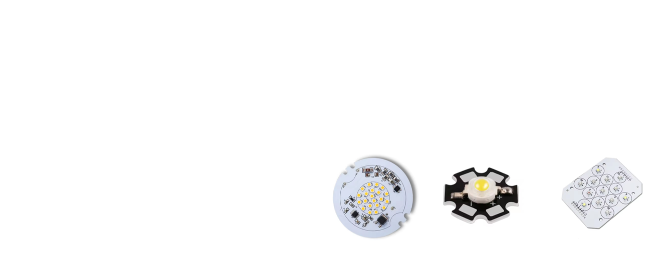
Applications of led ring light pcb?
- Application in medical equipment
The rapid progress of medicine is closely related to the rapid development of the electronics industry. Many medical devices are made of basic PCBs alone, such as pH meters, heart rate sensors, temperature measurements, electrocardiographs, electroencephalographs, MRIs, X-ray machines, CT scanners, blood pressure machines, blood sugar level measuring equipment, etc. - Application in industrial equipment
PCBs are widely used in manufacturing, especially in industries with high-power mechanical equipment; these devices run on high power and require high current circuit drive. Such as arc welding, large servo motor drives, lead-acid battery chargers, clothing cotton machines, etc. - Application in lighting
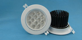
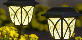
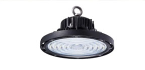
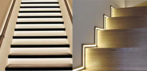
LED lights and high-intensity LEDs are mounted on PCBs based on aluminum substrates; aluminum has the property of absorbing heat and dissipating it in the air. - Application in the automotive and aerospace industries
Flexible PCBs are lightweight but can withstand high vibrations. Because of their light weight, they can reduce the total weight of spacecraft; flexible PCBs can be adjusted even in narrow spaces. These flexible PCBs are used as connectors, interfaces, and can be assembled even in compact spaces
FAQs About led ring light pcb
What is the thermal conductivities and withstanding voltages of BT/FR4 layer and Dielectric layer?
The SinkPAD conducts heat primarily through the copper base (400W/m.K), the withstanding voltages of Dielectric layer is around 4KV.
What is the placement accuracy for the SMT components?
+/-0.05mm is our SMT accuracy tolerance. You are welcome to come to our SMT factory in Shenzhen China and Vietnam.
Can the aluminum be made as the base of sinkpad MCPCB?
Actually, the sinkpad can only use copper as the base.
As you can see the below manufacturing steps, the SinkPad will etch the copper base into convex platform with Copper Etching Solution, then hollow out the Double Layer FR4 PCB, and do lamination with the convex platform.
However, regarding of current technical conditions, since aluminum or aluminum alloy cannot directly react with acid, the reaction process is too complex and difficult to control, which will increase the difficulty of etching the LED pad platform. Considering the scrap rate, the process of etching LED pad platform with aluminum is more complex and the overall cost is higher.
Can I plated copper in mcpcb via holes?
Generally speaking, copper plating through holes requires hole rings, otherwise the copper in the hole wall will easily fall off.
In addition, if it is a copper substrate, through the hole first to resin plug before copper plating.
Otherwise there’s no chemical reaction between copper and copper. And if the copper layer is connected to each copper layer, it is easy to short circuit.
Are you UL certified led pcb manufacturer?
Yes, we are UL certified manufacturer, our UL is E475635. We have already passed UL certificated. Meanwhile, we are passed ISO9001, ISO13485 and IATF16949 certifications.
Our LED pcbs are manufactured under highly monitored by these quality system controls.
How does the conveity of sinkpad manufactured?
Actually the sinkpad can only use copper as the base.
As you can see the below manufacturing steps, the SinkPad will etch the copper base into convex platform with Copper Etching Solution, then hollow out the Double Layer FR4 PCB, and do lamination with the convex platform.However, regarding of current technical conditions, since aluminum or aluminum alloy cannot directly react with acid, the reaction process is too complex and difficult to control, which will increase the difficulty of etching.