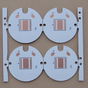
What is MCPCB prototype circuit board?
MCPCB prototype refers to the manufacture of a small number of sample PCB boards before formal mass production, and actual welding and testing to verify the correctness, performance and reliability of the design. This process is usually called “proofing” or “prototype production”. The main purpose of MCPCB prototype is to conduct trial production before mass production of circuit boards to ensure the feasibility of the design and the quality of the product. Through MCPCB prototype, design engineers can find and solve potential problems before actual production, thereby ensuring the performance and reliability of the final product.

Why do we need prototype model?
MCPCB prototypes are to verify the correctness and performance of the design and ensure the quality and reliability of the final product. By making MCPCB prototypes, developers can better optimize product designs, discover potential problems and deficiencies through testing, and make targeted improvements and optimizations.
1. Verify the correctness of the design: By making sample boards for testing, design problems can be found, such as errors in component layout and line connection. By discovering problems in advance and making modifications, problems can be avoided during mass production, saving time and cost.
2. Evaluate the performance of the circuit board: Through proofing tests, the working condition of the circuit board, signal transmission quality, power supply stability and other aspects can be checked to ensure the reliability and stability of the final product.
3. Improve the manufacturing process: During the sample board production process, manufacturing problems can be found, such as poor pads and unreliable line connections, so as to adjust the manufacturing process and workflow in time to improve the overall manufacturing quality and efficiency.


What files are needed to MCPCB prototype ?
1. Gerber file: contains the layer information of PCB, such as pads, connections, jacks, etc., and is the basic file for PCB manufacturing.
- BOM (Bill of Materials) list: lists the detailed information of all components on the PCB, including component model, quantity, etc., for procurement and assembly.
3. Drilling file: contains the location and size information of all holes punched on the PCB, which is very important for the manufacturer to perform drilling processing.
4. Circuit diagram: provides the connection method of the design, which is very important for checking whether the connection of the design is correct.
5. Special layer file: If the design requires special processes, such as impedance control or metallized hole wall, the corresponding special layer file needs to be provided.
★★Detailed explanation of the role and importance of each file:
★★Installation instructions and precautions: Provide detailed installation instructions, including information such as component direction and polarity, as well as the processing methods of special components
★★Material and thickness instructions: Specify the substrate material, plate thickness, copper foil thickness and other information used to ensure the accuracy of the production process.

What files are needed to MCPCB prototype ?
Prototype pcb manufacturing process
- Design phase:
Draw schematics: Use PCB design software (such as Altium Designer, Eagle, KiCad, etc.) to draw circuit schematics and perform error checking.
Generate PCB files: Generate PCB files based on schematics and component libraries, and set parameters such as number of layers, size, line width, and vias.
Export Gerber files and drill files: Gerber files describe PCB layers, and drill files describe via positions and sizes. These files are the main files required by board manufacturers.
- Production phase:
Place an order to make PCBs: Package and compress Gerber files and drill files, upload them to the website or software of the board manufacturer, and select appropriate parameters and quantities to place an order and pay.
Wait for delivery: The board manufacturer produces PCBs according to the order and sends them to customers by express delivery, which usually takes a few days to a week.
- Subsequent processing (if SMT patch is required):
Transform the schematic diagram and package library: Identify the component type and direction for the patch machine, and modify the schematic diagram and package library.
Export SMT patch coordinate file and bill of materials (BOM): The SMT patch coordinate file describes the component position and angle, and the bill of materials describes the component type and quantity.
- Order SMT patch: On the website or software of the board manufacturer, select whether SMT patch is required, and upload relevant files to place an order.
Waiting for delivery: The patch manufacturer performs SMT patch according to the order and sends it to the customer by express delivery.
Testing phase: Test with a flying probe tester to detect defects that affect functionality, such as open circuits and short circuits.


The difference between MCPCB prototype and copy board
The main differences between MCPCB prototypes and copy boards lie in the process flow, production cycle, cost, and applicable scenarios.
- Different process flow: Proofing is produced according to the design documents, usually through preparation, board making, drilling, plug-in, welding, coating and other process flows, and finally form a sample consistent with the design documents. Copy board is to reverse design and produce the existing PCB board, generally only need to carry out two process flows of plate making and etching.
- Different production cycle: Proofing has a longer production cycle, generally it takes 1-2 weeks to produce samples, mainly because it needs to go through multiple process flows, and the manufacturer needs to carry out strict quality control. Copy board production cycle is relatively short, generally only 3-5 days to produce a copy of the same effect as the original board.
- Different cost: Proofing costs are higher, because proofing requires multiple sample production and testing, plus the production cycle is longer, manufacturers need to invest more manpower and material resources.
Copy board costs less, because it only needs to be reverse designed and produced once, and the production cycle is short, so the cost is lower. - Different applicable scenarios:
Proofing is suitable for scenarios where the performance and reliability of PCB boards need to be verified and tested, such as the research and development stage of new products, verification of new technologies, etc.
Copy board is suitable for scenarios where a large number of PCB boards consistent with the original need to be produced quickly, such as mass production, repair and replacement, etc.
How much does a MCPCB prototype cost?
- Basic costs: including manufacturing costs, material costs and labor costs. Manufacturing costs include depreciation of production equipment and equipment maintenance costs; material costs mainly refer to the costs of PCB boards, and the prices of different types of boards vary greatly; labor costs include the labor costs of design, board making, welding and other processes.
- Process costs: calculated according to the customer’s special requirements for PCB boards, such as multi-layer boards, blind holes, buried holes, impedance control and other advanced processes will increase costs. The more layers, the higher the manufacturing difficulty and cost; the processing of special holes requires more sophisticated equipment and technology, so it will increase costs; impedance control In order to meet the stability of signal transmission, impedance control of PCB boards is sometimes required, which will also increase certain costs.
- Logistics costs: mainly include express delivery costs and insurance costs. It is calculated based on the number and weight of PCB boards, as well as the distance between the place of shipment and the place of receipt. In order to ensure the safety of goods during transportation, customers can choose to purchase insurance, and this part of the cost will also be added to the proofing price.
- Other costs: including taxes, surcharges, etc. According to the tax laws of different countries and regions, customers may need to pay corresponding taxes; if customers require expedited services or special services, additional fees may be incurred.
Why do prototypes cost so much?
1. Material cost: Multilayer PCBs require more substrates and prepregs, and the quality of these materials directly affects the functionality and reliability of the circuit. Although using high TG (glass transition temperature) materials will increase costs, it can improve the stability of PCBs in high temperature environments.
2. Manufacturing process: The production process of multilayer PCBs is more complicated, involving multiple pressing, drilling, and copper plating processes. These steps require sophisticated equipment and technology, which pushes up production costs.
3. Design complexity: The design of multilayer PCBs is usually more complex, involving more circuits and more compact spatial layout. Designers need to invest more time and energy in design optimization to ensure signal integrity and electromagnetic compatibility.
4. Testing and verification: To ensure that the performance of multilayer PCBs meets the standards, rigorous testing and verification are required, including electrical testing, thermal stress testing, etc., which adds additional costs.
5. Quantity and delivery time: The number of samples and the delivery time required by the customer will also affect the price. Urgent orders often require additional expedited fees.
6. Documentation and component research: The quantity and quality of documentation that may need to be completed to accompany the prototype build, and the manufacturer must update or create the necessary documentation to proceed with the build. Components in the design may need to be improved, and component engineers will need to spend time researching suitable alternatives.
7. Engineering analysis: The design may be more conceptual rather than production-ready, requiring more engineering analysis to ensure that potential manufacturing errors have been corrected.
8. Design and debug: It is often necessary to include more elements, such as design for assembly, design for test, and design for debug. Debugging design is essential in prototyping.