What is Resistance in a Circuit Board?
Resistance in a circuit board determines how easily electric current flows through the board. Every component and trace on the board offers some resistance, but the goal is to minimize it. Resistance happens when the flow of electrons is blocked or slowed down by the material they travel through. This blockage causes energy loss, often as heat.
In printed circuit boards (PCBs), low resistance is preferred in traces and paths to ensure smooth current flow. However, resistors are intentionally added in circuits to control and manage current flow, protecting sensitive components.
What is the Base of a Circuit Board?
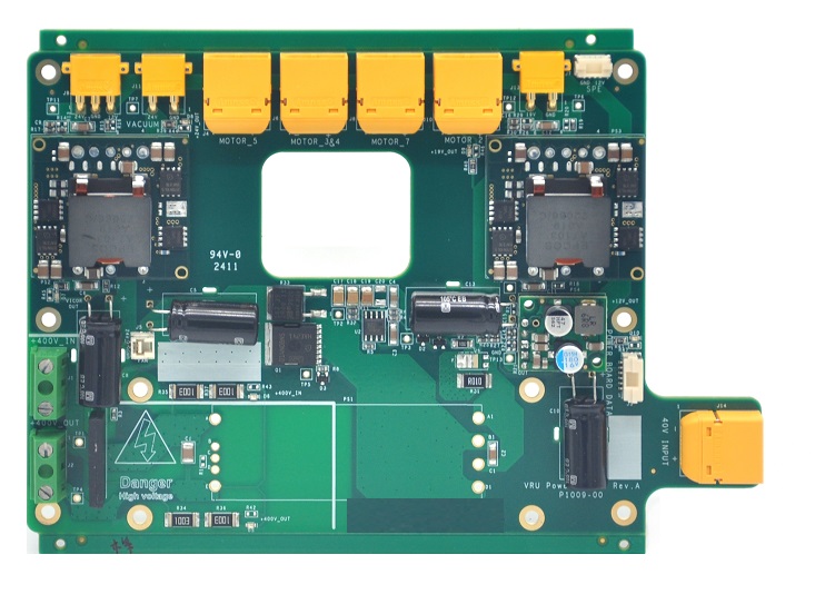
The base of a circuit board is the foundation on which components are mounted and connected. The copper layers, laminated onto the base, provide the conductive pathways that allow current to flow between components. It usually consists of layers of different materials, including a non-conductive substrate like fiberglass, often referred to as FR4. Some other materials also can be used as the base of circuit board, like:
- Glass fiber cloth substrate: commonly used in the production of double panels and multi-layer boards, with good mechanical properties and cost effectiveness.
- Paper substrate: lower cost suitable for cost-sensitive applications.
- Epoxy resin substrate: it has good mechanical properties and thermal stability, widely used in electronic products
- Polyimide substrate: it has excellent high temperature resistance, suitable for high performance electronic products.
- Polytetrafluoroethylene (PTFE) substrate: very high temperature resistance and low dielectric constant, suitable for high frequency and high temperature environments.
- Ceramic substrates: such as alumina, aluminum nitride, etc., with high thermal stability and low dielectric constant, suitable for extreme environments.
- Teflon (ETFE) substrate, it has good corrosion resistance, high frequency properties and low dielectric constant.
- Metal substrates: metal materials like aluminum or copper are always serve as the base of metal core PCBs, they have very good thermal conductivity, and suitable for high power applications where need good heat dissipation.
How Does a Basic Circuit Board Work?
The basic circuit board connects various electronic components through conductive paths called traces, and performs specific functions through the interaction of electronic components. These tracks are made of copper and are designed to create specific circuits that control the flow of electricity. The circuit board uses insulating materials to isolate the conductive layer of copper foil on the surface, so that the current flows in each component along the pre-designed path to complete the functions of work, amplification, attenuation, modulation, demodulation, coding and so on.
Components such as capacitors, resistors, transistors, and diodes are soldered onto the board. The current flows through the components, following the paths designed in the layout, executing the required tasks, such as powering an LED or processing signals.
For the circuit to work, all components must be properly connected and powered. Any break in these connections can disrupt the flow of current, leading to malfunctions.
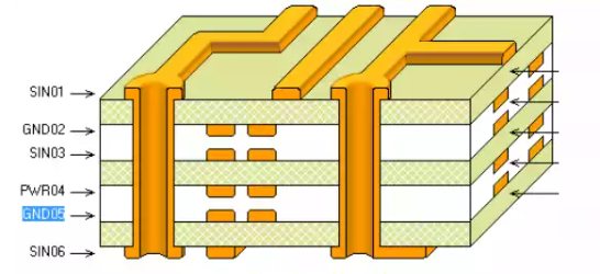
The main components and functions of the circuit board:
- Pad – metal holes for welding the pins of components.
- Through hole – there are metal through holes and non-metal through holes, used to connect the component pins between each layer.
- Conductor – the conductive path connecting electronic components.
- Components – such as resistors, capacitors, inductors, etc., are connected to each other by conducting lines.
- Connector – used to connect external devices.
- Electrical boundary – defines the electrical characteristics of the board.
Does an Open Circuit Have Low Resistance?
No, an open circuit has high resistance, often considered infinite.
Open circuit refers to the circuit state when no current passes between two points in the circuit or is connected by a conductor with a very large impedance value (or resistance value). When the branch between two points in the circuit is open, the potential difference between the two points is called “open voltage” and can be measured by a voltmeter. In the open state, because there is no current flow, the resistance is very high, this is because the current path in the open circuit is interrupted, resulting in the current cannot flow, so that the resistance in the open state is extremely high â
In contrast, a short circuit refers to the situation where the current does not pass through the electrical appliance and directly constitutes a path. In a short circuit, the resistance in the circuit is small, because the current flows directly through the wire, rather than through the load, resulting in a large current. In this state, the fuse may automatically blow due to excessive current, to prevent the wire from causing a fire due to heat â
How to Tell If a Circuit Board is Shorted?
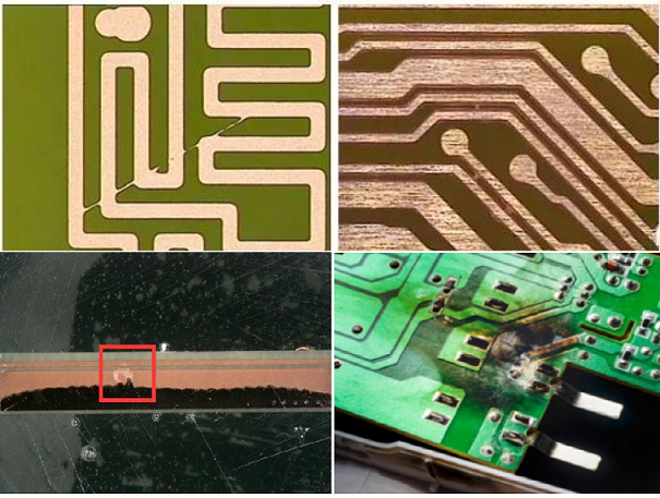
Identifying a shorted circuit board involves looking for signs like:
- Burn marks or discoloration on the board.
- Swollen or damaged components.
- Overheating, causing the board to feel hot to the touch.
- The device or board not powering on or malfunctioning.
To confirm a short, a multimeter can be used. By measuring the resistance between points where there should be separation, a very low resistance could indicate a short. This can help pinpoint faulty components or traces.
How to Check Resistors on a Circuit Board?
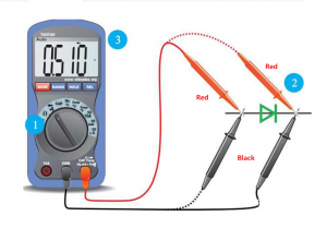
To check resistors on a circuit board, you can use a multimeter in resistance mode.
- Turn off the power to the board and discharge capacitors to avoid any residual current.
- Set the multimeter to the appropriate resistance range.
- Place the probes across the resistorâs terminals and read the value displayed on the meter.
Compare this value with the expected resistance value, usually printed on the resistor or found in the circuitâs schematic. A large discrepancy could indicate a faulty resistor.
How Are Circuit Boards Grounded?
Circuit boards are grounded by connecting the ground plane, often a large layer of copper, to a grounding point. The grounding modes of the circuit board mainly include single point grounding, multi-point grounding, floating ground and virtual ground. â
- Single-point grounding
Single-point grounding â is suitable for low-frequency circuits where only one physical point in the entire circuit system is defined as the grounding reference point and all other points that need to be grounded are directly connected to this point. This approach can reduce common ground impedance coupling and low-frequency ground loop interference, and is usually used for circuits with frequencies less than 1MHz.
- Multi-point grounding
Multipoint grounding â is suitable for high-frequency circuits, where each ground point of the electronic device is directly connected to the nearest ground plane (that is, the metal base plate of the device). This method can reduce the interference generated by the common ground impedance, and also reduce the parasitic capacitance and inductance, which is usually used for circuits with frequencies greater than 10MHz.
- Floating ground
âFloating â that is, the ground of the circuit is connected to the ground without a conductor, but at a higher potential. The advantage of floating ground is that the circuit is not affected by geoelectrical properties, and can prevent electromagnetic interference caused by the coupling of common ground impedance circuits. However, the disadvantage of this method is that it is affected by the parasitic capacitance, which leads to the change of ground potential and increases the inductive interference to the analog circuit.
- Virtual ground
Virtual ground â is similar to floating ground and can be understood as the “floating ground” when the operational amplifier is short and broken.
What is the Rule for Resistance in a Circuit?
The fundamental rule of resistance is governed by Ohm’s Law: V=IR, where voltage (V) is equal to the current (I) multiplied by resistance (R). This shows that the resistance directly affects how much current flows for a given voltage.
In circuits, resistors are used to control current, and their value determines how much current is allowed through. For example, higher resistance lowers the current flow, while lower resistance allows more current to pass.
With over 18 years as an industry leader, Best Technology is one of the most experienced PCB and PCB assembly manufacturer in Asia. We are highly specialized not only in quick-turn PCB prototype and PCB assembly, but also medium and small volume PCB fabrication. In Best Technology, you can enjoy a full-comprehensive one-stop service from PCB design, layout, PCB fabricate, PCB assembly, function testing and delivery. We always try our best to fabricate your PCB with copper clad laminate with the highest quality to meet your demands.
If you have any questions, please feel free to contact us with sales@bestpcbs.com, we will be happy to help you.


