In today’s highly digitalized and interconnected world, high frequency PCB communication circuits play a vital role. Whether in the fields of high-speed data transmission, wireless communications, satellite communications or radar systems, high frequency PCB communication circuits have demonstrated their unique advantages and importance.
What is high frequency PCB?
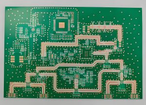
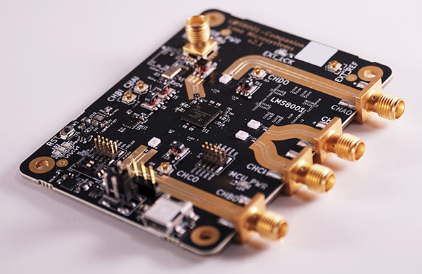
high frequency PCB communication circuits refer to printed circuit board circuits that operate in a higher frequency range, usually between hundreds of MHz and tens of GHz. Compared with traditional low-frequency PCB circuits, high frequency PCB communication circuits have the following significant characteristics:
- 1. High-speed signal transmission: high frequency PCB communication circuits can support high-speed data transmission and meet the needs of modern communication systems for large data volumes and high bandwidth.
- 2. Low signal loss: At high frequencies, signal transmission loss will increase significantly. Therefore, high frequency PCB communication circuits require special materials and design techniques to reduce signal loss and improve signal transmission quality.
- 3. Good electromagnetic compatibility: high frequency signals are prone to electromagnetic interference and affect surrounding electronic equipment. high frequency PCB communication circuits need to have good electromagnetic compatibility to ensure their stable operation in complex electromagnetic environments.
- 4. Miniaturization and lightweight: As electronic equipment continues to be miniaturized and lightweight, high frequency PCB communication circuits also need to develop in the direction of miniaturization and lightweight. This requires the use of high-density integration technology and advanced manufacturing processes to reduce the size and weight of circuit boards.
How do you make high frequency PCB?
Making a high frequency PCB (printed circuit board) involves several key steps to ensure the stability and reliability of signal transmission, taking into account the characteristics of high frequency signals.
1. Material selection and preparation:
- Choose a substrate material with low dielectric constant and low dielectric loss to ensure the stability and reliability of signal transmission.
- The substrate material requires a conductive layer with good electrical conductivity and corrosion resistance.
- Auxiliary materials such as membrane materials, filling materials, etc. also need to be carefully selected and prepared.
2. Design, drawing production, etching, and laminating:
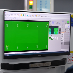
- Carry out circuit design and layout planning based on design requirements and signal transmission characteristics.
- Make PCB drawings and convert circuit layout and connection lines into circuit diagrams on the drawings.
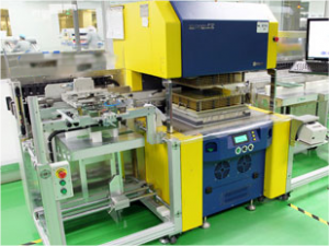
- The circuit diagram on the drawing is transferred to the substrate through photolithography technology and etched to form a conductive layer.
- The film sticking process attaches the protective layer and copper clad layer to the conductive layer to protect the circuit and improve the mechanical strength.
3. Welding and assembly process:
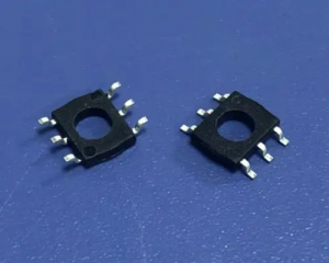
- Surface mount technology is widely used in high frequency PCB welding, and SMT components are accurately welded to PCBs through methods such as hot air or reflow soldering.
- Manual soldering technology also plays an important role in the assembly of high frequency PCBs. Plug-in components and connecting lines are connected by manual soldering.
4. Special considerations for high frequency PCBs:
- high frequency circuit design requires the adoption of special design principles and strategies, such as transmission line theory and matching, short and straight wiring strategies, impedance control and matching, decoupling and bypass, etc., to ensure signal quality and system reliability.
- Adopt strategies such as multi-layer board design, straight wiring, shortening signal leads, reducing inter-layer alternation, being wary of crosstalk, increasing decoupling capacitors, isolating digital and analog ground wires, avoiding loops, ensuring impedance matching, and preventing ground bounce to improve Performance and reliability of high frequency circuits.
- Through the above steps, a high-quality PCB that meets high frequency signal transmission requirements can be produced to ensure stable signal transmission and reliable operation of the system.
What are some important considerations when designing a PCB layout for high frequency circuits?
Designing high frequency PCB communication circuits faces many challenges and requires comprehensive consideration of circuit performance, electromagnetic compatibility, reliability and other aspects. Here are some of the major design challenges:
- 1. Signal integrity: At high frequencies, signal transmission will be affected by reflection, crosstalk, attenuation and other factors, leading to signal integrity problems.
- 2. Electromagnetic compatibility: As mentioned before, high frequency signals are prone to electromagnetic interference, so high frequency PCB communication circuits need to have good electromagnetic compatibility.
- 3. Thermal management: high frequency PCB communication circuits will generate a large amount of heat when working. If the heat cannot be dissipated in a timely and effective manner, the performance of the circuit will be reduced or even damaged.
- 4. Reliability: high frequency PCB communication circuits usually work in harsh environments, such as high temperature, high humidity, vibration, etc.
What is the highest frequency used for communication?
The highest frequency used for communication is 450GHz.
This frequency range was finally approved at the 2019 World Radiocommunication Conference (WRC-19) and involves the 275 GHz-296 GHz, 306 GHz-313 GHz, 318 GHz-333 GHz and 356 GHz-450 GHz frequency bands, for a total of 137 GHz Bandwidth resources.
These frequency bands are used without restrictions for fixed and land mobile service applications. This is the first time that ITU has clarified the spectrum resources available for terrestrial active radio service applications in the terahertz frequency band above 275 GHz, and raised the upper limit of available spectrum resources for active services to 450 GHz, providing basic resource guarantee for the development and application of the global terahertz communication industry. .
Which frequency is best for communication?
For WiFi communication, choosing which frequency band is best depends on the user’s specific needs and network environment.
- The 2.4GHz frequency band is suitable for use in home and office environments because of its strong signal penetration and low interference, especially when wide coverage and signal stability are required.
- Because of its high-speed transmission capabilities, the 5GHz band is suitable for scenarios that require large traffic transmission, such as high-definition videos and online games, because it provides faster network speeds and more stable transmission rates.
In satellite communications, different frequency bands have their own advantages and applicable scenarios.
- Although the C-band has low frequency and low gain, its rain attenuation is much smaller than that of the Ku-band and even smaller than the Ka-band. It is suitable for businesses that have strict requirements on communication quality, such as television and radio.
- The Ku band has high frequency, high gain, small antenna size, and is easy to install. It is especially suitable for mobile emergency communication services such as communication in motion and communication in silence, and satellite news collection SNG and DTH services.
When selecting the wireless communication frequency band bandwidth.
- The 20MHz frequency band bandwidth is suitable for small to medium-sized wireless networks due to its stable signal and wide coverage.
- Although the data transmission rate of the 40MHz band bandwidth is relatively high, the signal penetration capability is weak and is suitable for dense environments or application scenarios that require higher transmission rates.
What are examples of high frequency equipment?
high frequency PCB communication circuits are widely used in various fields. The following are some of the main application fields:
- 1. Wireless communication: high frequency PCB communication circuits are the core components of wireless communication systems, such as mobile phones, base stations, satellite communications, etc.
- 2. Radar system: high frequency PCB communication circuits are also widely used in radar systems, such as radar antennas, signal processing, transmitters and receivers, etc.
- 3. Satellite communications: Satellite communications require the use of high frequency PCB communication circuits to transmit and receive signals.
- 4. High-speed data transmission: In the field of high-speed data transmission, high frequency PCB communication circuits can achieve data transmission rates of tens of Gbps per second to meet the needs of large data volume and high bandwidth.
In short, high frequency PCB communication circuits are an important part of modern communication technology and have broad application prospects and development potential. With the continuous advancement of technology.