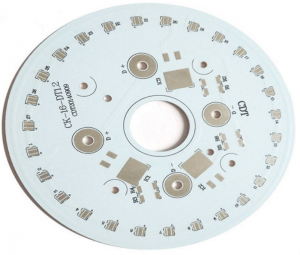
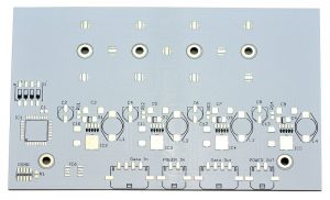
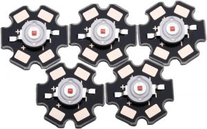
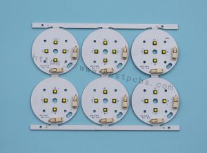
In the electronic manufacturing process, it is usually necessary to divide a large area of aluminum-based PCB into multiple small pieces so that they can be installed in different electronic devices. Different electronic devices have different requirements for the size of PCBs. Through depaneling, large-area aluminum-based PCBs can be cut into sizes suitable for specific electronic devices.
What is the meaning of depaneling?
Aluminum PCB depaneling refers to cutting multiple circuit boards arranged in a row from a large board into separate small boards. This process is to divide a large aluminum printed circuit board (PCB) into multiple independent and fully functional circuit boards for subsequent assembly and use.
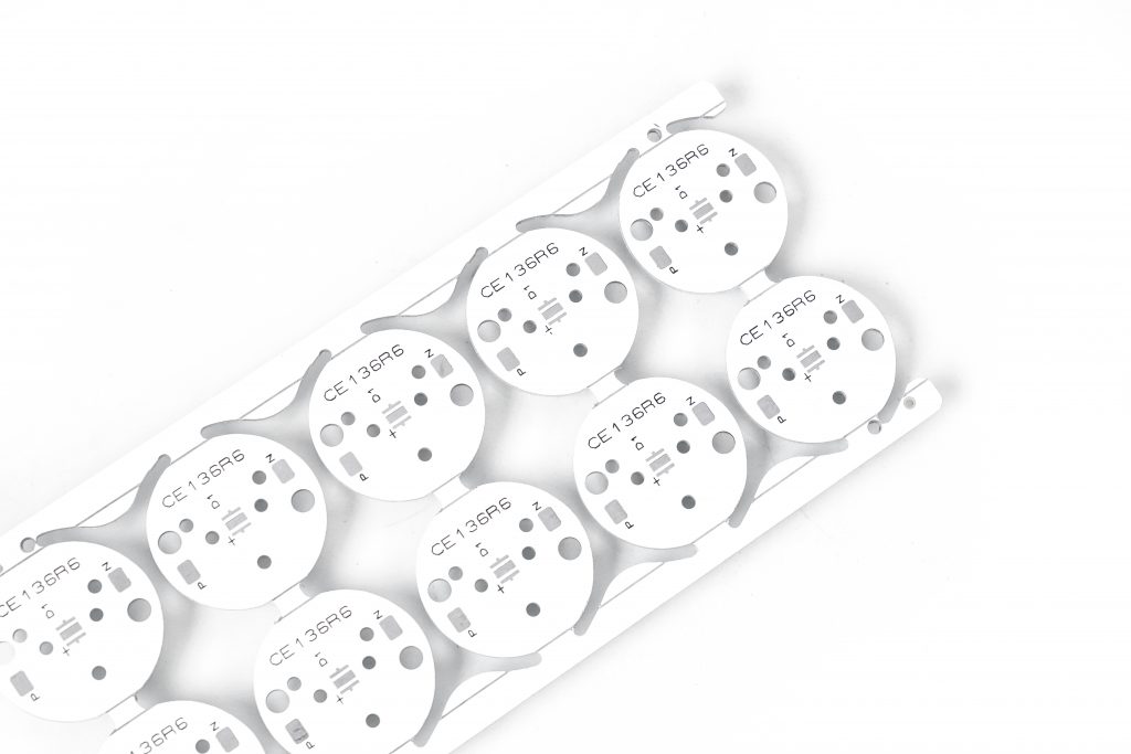
Aluminum PCB depaneling is an important link in the production process of electronic devices, which can improve production efficiency and circuit board flexibility.
What are the methods of PCB depaneling?
There are many ways to depanel aluminum PCBs. Common depaneling methods include:
- 1. V-cut depaneling: Use a V-shaped blade to cut a V-shaped groove on the PCB board, and then separate the aluminum PCB along the groove by external force. This method is suitable for smaller aluminum PCB boards and fine dividing lines.
- 2. Sawtooth depaneling: Cut the aluminum PCB board with a sawtooth cutting tool to form multiple small panels, and then separate the panels by pressure or vibration. This method is suitable for aluminum PCB boards with larger areas.
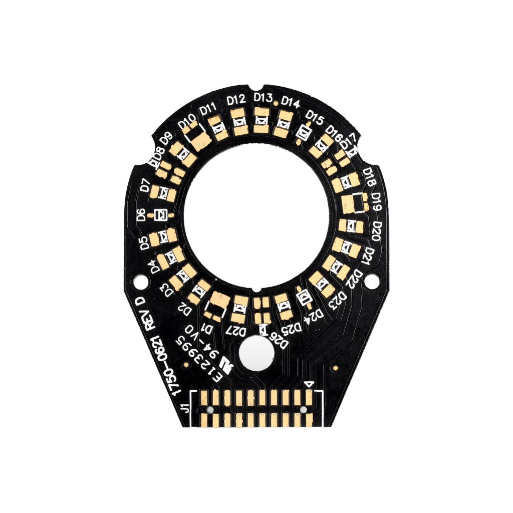
- 3. Laser depaneling: Use a high-energy-density laser beam to accurately cut the aluminum PCB, which is suitable for production environments with high precision requirements and high efficiency.
- 4. Chemical corrosion depaneling: Corrode the aluminum PCB with a chemical corrosive agent to form a dividing line, and then separate the panels by physical methods.
What is the process of depaneling PCB?
The aluminum PCB depaneling process varies depending on the depaneling method. The common aluminum PCB depaneling methods and processes are as follows:
Manual depaneling
- Preparation: Check whether the aluminum PCB board meets the conditions for manual depaneling, such as confirming that there are no stress-sensitive components such as SMD (Surface Mounted Devices) on the board, and prepare suitable fixtures and operating space.
- Positioning and fixing: Place the aluminum PCB concatenated or assembled boards that need to be separated on a stable workbench and fix them with fixtures to ensure that the boards do not move during the separation process. For aluminum PCB boards with V-grooves, align the V-grooves with the direction that is convenient for force application, and ensure that the board is placed in the correct direction and position to facilitate the separation operation.
- Separation operation: The operator uses both hands or simple tools (such as tweezers, etc., and small cutting tools may be used in some special cases, but they must be operated with caution to avoid damaging the board) along the V-groove to break or separate the aluminum PCB board into individual small boards with appropriate force. During the operation, pay attention to controlling the force and direction to avoid damage to the board due to uneven force or wrong direction.
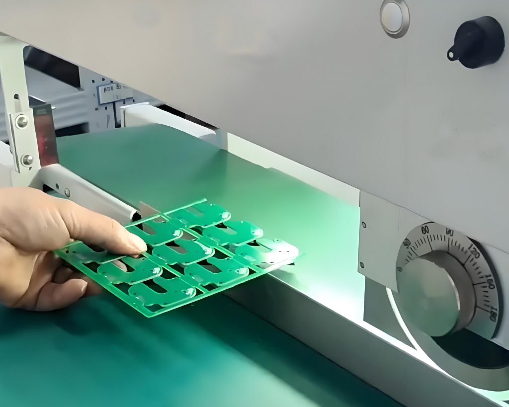
V-cut board separation machine separation
- Equipment debugging: Turn on the power of the V-cut board separation machine, and adjust the upper guide knife position and lower knife height of the board separation machine according to the thickness of the aluminum PCB board, the depth and width of the V-groove and other parameters to ensure that the spacing between the upper and lower knives is appropriate and the aluminum PCB board can be accurately cut.
- Upper board positioning: carefully place the aluminum PCB board with V groove on the workbench of the V-cut board splitter, ensure that the V groove of the aluminum PCB board fits tightly with the lower knife of the board splitter, and the position of the board is accurate to avoid deviation during the cutting process.
- Board splitting operation: start the V-cut board splitter manually, electrically or pneumatically, so that the blade cuts along the V groove of the aluminum PCB board. During the cutting process, pay attention to the cutting situation to ensure that the cutting depth is moderate and will not cause over-cutting or incomplete cutting of the aluminum PCB board.
What is the manufacturing process of aluminum PCB?
The manufacturing process of aluminum substrate PCB mainly includes the following steps: cutting, drilling, dry and wet film imaging, etching, surface treatment and final inspection.
- 1. Cutting: Cut the large-sized incoming materials into the size required for production, pay attention to the protection of the aluminum and copper surfaces, and avoid scratches and board edge delamination.
- 2. Drilling: Position the holes in the board to ensure the correct number and size, and avoid scratches on the board and deviation of the hole position.
- 3. Wet and dry film imaging: Present the parts required for making the circuit on the board, and pay attention to whether the circuit is open and whether the alignment is deviated after development.
- 4. Etching: Remove the uncovered parts to form the circuit pattern, and pay attention to the quality and stability of the circuit after etching.
- 5. Surface treatment: Perform necessary surface treatment on the circuit board, such as tin spraying, to improve the performance and appearance of the circuit board.
- 6. Final inspection: Perform a final inspection on the completed circuit board to ensure that the quality meets the requirements.
What are the advantages of aluminum PCB?
The main advantages of aluminum substrate PCB include:
- Excellent heat dissipation performance: The aluminum substrate uses high thermal conductivity aluminum alloy as the core material, which can quickly conduct and dissipate heat, thereby effectively reducing the operating temperature of components.
- Lightweight design: Compared with traditional FR4 substrates, aluminum substrates have lighter weight, which is particularly important in weight-sensitive fields such as aerospace and automobiles, helping to reduce the weight of the overall equipment and improve energy efficiency and operating performance.
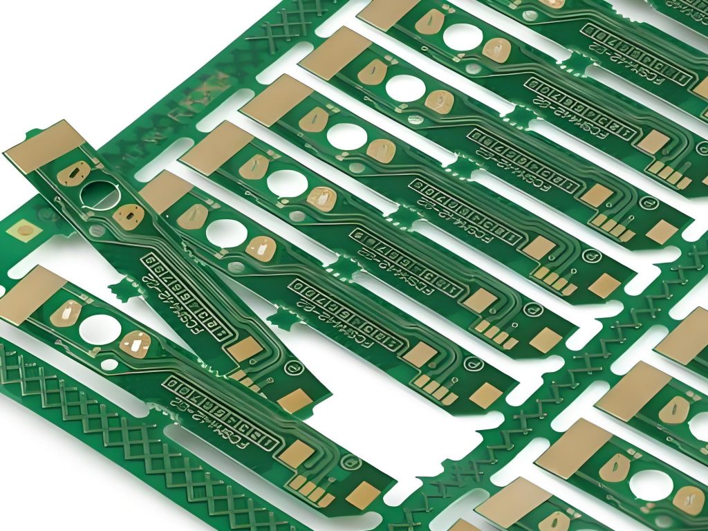
- Good mechanical properties: Aluminum substrates have high strength and hardness, providing good support and protection for electronic components. At the same time, its excellent impact resistance and vibration resistance enable it to adapt to various complex working environments and ensure the stable operation of the equipment.
- Excellent electrical performance: Aluminum substrates have excellent insulation and voltage resistance, which can meet the electrical requirements of electronic equipment in various working environments and provide stable electrical support for the equipment.
- Environmental protection: Aluminum substrates are made of environmentally friendly materials, there is no pollution in the production process, and waste is easy to recycle and dispose, which is fully in line with the current trend of green environmental protection.
- Diverse application forms: There are many types of aluminum substrates, including flexible aluminum substrates, hybrid aluminum substrates, multi-layer aluminum substrates, etc., suitable for different application needs.
What are the disadvantages of aluminum PCB?
The main disadvantages of aluminum PCB include high cost, difficult process, electrical strength and withstand voltage problems, mismatched thermal conductivity test, inconsistent material specifications, and more defective products.
First, the price of aluminum PCB is relatively high, usually accounting for more than 30% of the product price. This is because the production of aluminum PCB requires the use of high-purity aluminum materials and special processing technology, all of which push up the cost.
Second, the process of aluminum PCB is difficult, especially when it is made into a double-sided board, the process complexity is higher, and it is easy to have problems in electrical strength and withstand voltage. In addition, the mismatch of thermal conductivity test methods and results of aluminum PCB is also a problem.
In addition, the material specifications of aluminum PCB have not yet been unified, and there are multiple standards such as CPCA industry standards, national standards, and international standards, which brings certain uncertainties to production and application.
Why is aluminum no longer used in integrated circuits?
The main reason why aluminum is no longer used in integrated circuits is that copper has replaced aluminum as an interconnect metal material. Copper has lower resistivity and better anti-electromigration performance than aluminum, which makes copper more reliable and effective in high-speed integrated circuits.
Specifically, aluminum may experience electromigration under long-term current, that is, aluminum atoms migrate inside the wire, causing the wire to break or form voids, which in turn causes the integrated circuit to fail. In addition, as the interconnection spacing decreases, the resistance of the aluminum wire increases and the capacitance between the wires increases, resulting in increased RC delay, which is not conducive to high-speed integrated circuits.
Copper has a lower resistivity than aluminum, can transmit current more efficiently, and can carry more current in thinner metal wires. Copper also has higher electromigration resistance than aluminum, making copper interconnects more reliable under high current conditions. These advantages make copper a preferred material for advanced integrated circuit technology.
Aluminum-based PCB depaneling is an important link in the electronic manufacturing process, which directly affects the quality and performance of electronic equipment. By selecting the appropriate depaneling method, controlling the depaneling accuracy, and avoiding damage to the PCB, the quality and efficiency of aluminum-based PCB depaneling can be effectively improved.
Tags: aluminum pcb, MCPCB, PCB, printed circuit board


