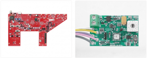
What Is a PCB Input Jack?
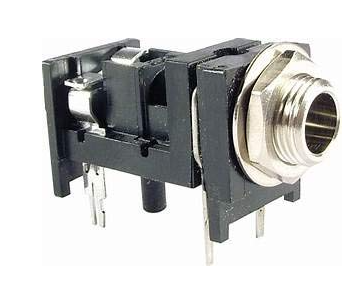
A PCB input jack is a connector that establishes a physical link between an external device and a PCB. These connectors serve as entry points for power, data, or audio signals, depending on the application. There are various types of input jacks, such as mono jacks, stereo jacks, and different connector formats like 3.5mm, 6.35mm (1/4 – inch), and more. A mono jack has two connections (tip and sleeve), while a stereo jack typically has three (tip, ring, and sleeve). The tip is usually for the positive signal, the sleeve is for the ground, and in a stereo jack, the ring is for an additional channel (like the right channel in audio applications).
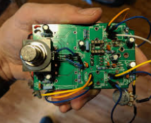
Before wiring, you need to understand the pin configuration of the specific input jack you’re using. This information is usually available in the datasheet provided by the manufacturer. For example, in a 3.5mm stereo jack, the tip might be connected to pin 1, the ring to pin 2, and the sleeve to pin 3.
What is the purpose of the input jack?
The purpose of an input jack is to serve as a connection interface between external devices and a PCB. It allows signals, power, or data to enter the circuit, enabling the PCB to communicate or interact with other devices. Input jacks are commonly used in various electronic applications, including:
1. Audio Transmission
In devices like headphones, speakers, or microphones, audio input jacks receive sound signals from external sources and transmit them to the circuit for processing or amplification.
2. Power Supply
Power jacks provide a pathway for external power sources to supply energy to a device. This is common in laptops, routers, and other electronics that require an external adapter.
3. Data Transfer
Input jacks such as USB or Ethernet ports allow data to flow between the PCB and external devices.
4. Signal Interface
In control systems and instrumentation, input jacks receive analog or digital signals from sensors or other control devices.
What should you do before Wiring?
Before the wring process, there are some preparation works to ensure a good soldering.
- Gather Tools and Materials
You’ll need soldering equipment, including a soldering iron, solder wire, and flux (if necessary). Also, make sure you have wire strippers and cutters. The wire you choose should be appropriate for the current and signal requirements of your circuit. For low – power audio applications, a stranded wire with a gauge like 22 – 24 AWG (American Wire Gauge) is usually sufficient.
- PCB Layout
Examine the PCB layout around the input jack area. There should be pads or through – holes designated for the jack connections. These are usually labeled according to the function (e.g., “Tip”, “Ring”, “Sleeve”, “GND”) or with pin numbers that match the jack’s pinout.
- Inspect PCB
Check the PCB for any damage, such as cracks or broken traces or dust on the Pads. Ensure the pads where the jack will be soldered are clean and free from oxidation.
Wiring PCB input jack- step by step
1. Stripping the Wire: Use wire strippers to carefully remove a short section (about 3 – 5mm) of insulation from the end of the wire that will connect to the input jack. Make sure not to nick or damage the wire inside the insulation.
2. Inserting the Wire: Insert the stripped end of the wire into the appropriate hole or onto the pad on the PCB corresponding to the jack’s connection point. For through – holes, the wire should pass through the hole so that a small portion is visible on the other side of the PCB.
3. Soldering
- Heat the soldering iron to the appropriate temperature (usually around 300 – 350°C for standard solder).
- Apply a small amount of solder to the tip of the soldering iron to tin it. This helps the solder flow more smoothly.
- Place the tip of the soldering iron against the wire and the pad or through – hole at the same time. Then, feed a small amount of solder onto the joint. The solder should flow around the wire and form a smooth, shiny joint. Avoid using too much solder, as it can lead to shorts between adjacent connections.
- After soldering, allow the joint to cool for a few seconds. You can use a pair of tweezers to hold the wire in place during cooling to ensure it doesn’t move and create a bad joint.
4. Post – Wiring Checks
- Visual Inspection: Examine each joint carefully to make sure there are no cold joints (where the solder didn’t properly adhere), shorts (unintended connections between different wires or pads), or other visible defects. A good solder joint should be smooth, shiny, and cover the wire and pad or through – hole completely.
- Continuity Testing: Use a multimeter to test the continuity between the input jack’s pins and the corresponding points on the PCB. Set the multimeter to the continuity or resistance measurement mode. For example, when testing the connection between the tip of the input jack and the PCB pad labeled “Tip”, the multimeter should beep (indicating a low – resistance connection) if the wiring is correct.
- Function Testing: If possible, connect the input jack to the appropriate input source (such as an audio signal generator for an audio input jack) and test whether the signal is correctly received and processed by the circuit on the PCB. This might involve using an oscilloscope or other testing equipment to monitor the signal at different points in the circuit.
How Do You Identify the Input Jack Pins?
Understanding the pin configuration of the input jack is crucial for proper wiring. While some jacks have labeled pins, others may require a closer inspection or reference to a datasheet. Letâs explore how to identify the pins for common types of jacks:
1. Audio Jacks (TRS and TRRS)
Audio jacks are classified based on their Tip, Ring, and Sleeve (TRS) structure.
Tip (T): Carries the left audio channel.
Ring (R): Carries the right audio channel.
Sleeve (S): Acts as the common ground.
For a TRRS (Tip, Ring, Ring, Sleeve) jack, the second ring often carries a microphone or additional signal.
2. Power Jacks
Power jacks typically have three pins:
Positive (VCC): Supplies power to the device.
Negative: Returns current to complete the circuit.
Ground (GND): Connects to the common ground of the PCB.
3. USB Jacks
USB jacks have multiple pins, each with a specific function:
VCC: Provides power to the connected device.
GND: Connects to the ground.
Data+ (D+): Transfers positive data signals.
Data- (D-): Transfers negative data signals.
Refer to the datasheet of your specific jack for accurate pin identification.
What Tools and Materials Do You Need?
Wiring a PCB input jack requires a few essential tools and materials. Having the right equipment ensures a clean, reliable connection:
- Soldering Iron: Used to melt solder and join components.
- Solder: The metal alloy that creates the electrical connection.
- Wire Stripper: Removes the insulation from wires.
- Tweezers: Helps position small components.
- Multimeter: Tests electrical connections for continuity and voltage.
- Flux: Enhances the flow of solder and improves the bond.
- PCB Holder: Secures the PCB in place during soldering.
How Can You Avoid Common Wiring Mistakes?
Wiring mistakes can lead to malfunctioning devices or damaged components. Hereâs how to avoid common pitfalls:
- Double-Check Pin Connections: Before soldering, ensure each wire is connected to the correct pin.
- Use Quality Solder: Cheap solder can lead to weak connections. Use a high-quality solder for better results.
- Avoid Cold Joints: Ensure the solder flows properly and bonds well with the pad and pin.
- Inspect for Shorts: Check for any solder bridges between pins, which can cause short circuits.
How Do You Test the Wired PCB Input Jack?
Testing is a critical step after wiring the input jack. It ensures all connections are secure and functional. Hereâs how to test your work:
1. Visual Inspection
Look for any obvious issues, such as loose wires, cold solder joints, or solder bridges.
2. Continuity Test
Use a multimeter to test the continuity between the jack and PCB pads. This verifies that the connections are intact.
3. Functionality Test
Connect the external device to the input jack and verify that it works as expected. Test for audio quality, power delivery, or data transfer, depending on the jack type.
Wiring a PCB input jack requires attention to detail and proper technique. Whether you’re wiring an audio jack, power jack, or USB port, preparation and testing are key to success. If you need high-quality PCBs with precise input jack placements, our company offers customized solutions to meet your needs. Contact us today to learn how we can support your next project with reliable PCB solutions.


