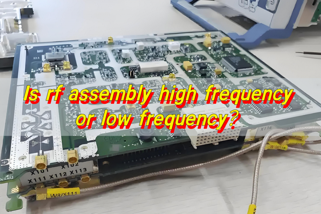
Is rf assembly high frequency or low frequency?RF components have a wide operating frequency range, covering multiple frequency bands from low frequency to high frequency. Generally speaking, the RF band generally refers to 3kHz to 300GHz, but in actual applications, 3kHz to 30MHz is often regarded as a low-frequency RF range, such as some simple wireless remote controls, while 30MHz to 300GHz belongs to high-frequency RF.
What is high-frequency vs low frequency?
Definition of high frequency and low frequency
- Low-frequency circuit: mainly used to process signals with lower frequencies, usually in the range of tens of hertz to several thousand hertz. Common applications include audio circuits, etc.
- High-frequency circuit: used to process signals with higher frequencies, usually in the range of several thousand hertz to several hundred megahertz. High-frequency circuits are very important in applications such as communications, radars, and satellites.
Differences between high frequency and low frequency in PCB design
- Power supply design: In high-frequency PCB design, the power supply design is usually one layer, which can minimize signal loops and thus reduce noise.
- Signal integrity: High-frequency PCB design requires special attention to signal integrity, including signal transmission delay, reflection and crosstalk.
Is RF high or low-frequency?
RF (radio frequency) is high frequency. It refers to the electromagnetic frequency that can be radiated into space. Its frequency range is from 300kHz to 30GHz, so it belongs to the high-frequency category. Alternating current that changes less than 1000 times per second is called low-frequency current, while alternating current that changes more than 10,000 times per second is called high-frequency current. RF is such a high-frequency current.
Basic characteristics of RF
- Frequency and wavelength: The frequency of RF is between 300kHz and 30GHz. The wavelength is inversely proportional to the frequency, that is, the shorter the wavelength, the higher the frequency. The frequency of RF is higher, so the wavelength is shorter.
- Amplitude and phase: The amplitude signal of RF represents the measure of the change of electric field oscillation, and the phase represents the position of a single time point in the wave cycle.
- Modulation: In order to achieve communication, the RF signal needs to be modulated. Modulation includes analog modulation and digital modulation, which uses frequency, phase and amplitude to transmit data.
What is the highest RF frequency?
The highest frequency of RF (radio frequency) is 300GHz. Within this frequency range, RF is widely used in fields such as radar and wireless communication.
The basic characteristics of RF include frequency, wavelength, amplitude and phase. Frequency refers to the frequency of electromagnetic field oscillation, measured in Hertz (Hz). Wavelength is inversely proportional to frequency, that is, wavelength is equal to the speed of light divided by frequency. The amplitude of RF refers to the measure of the change in electric field oscillation, while the phase indicates the position of a single time point in the wave cycle.
How do you know if the frequency is high or low?
In PCB design, judging whether the frequency is high or low is mainly based on the frequency range of the signal.
Definition of frequency range
- High frequency: usually refers to signals with frequencies between 3MHz and 300GHz. In PCB design, signals greater than 50MHz are generally considered high-speed signals, and signals with rising/falling edges less than 50ps are also considered high-speed signals.
- Low frequency: usually refers to signals with frequencies between hundreds of Hz and hundreds of kHz.
Specific applications in PCB design
- High-frequency PCB design: In high-frequency PCB design, the power supply design is usually one layer, which can minimize the signal loop and thus reduce noise. In addition, high-frequency signals are susceptible to interference, so special attention should be paid to noise issues in the design.
- Low-frequency PCB design: Low-frequency circuit design usually does not need to consider signal loops and noise issues too much, but it is still necessary to pay attention to signal integrity and electromagnetic compatibility.
Measurement methods and tools
- Oscilloscope: Oscilloscope is a common tool for measuring signal frequency. The frequency range of the signal can be judged by observing the waveform.
- Spectrum analyzer: Spectrum analyzer can measure the frequency component of the signal more accurately and is suitable for occasions requiring high-precision measurement.
What is high-frequency PCB?
High-frequency PCB is a special type of circuit board designed specifically for processing high-frequency signals, and its operating frequency can reach hundreds of megahertz (MHz) to tens of gigahertz (GHz). High-frequency PCB occupies a key position in high-frequency application scenarios such as wireless communication, 5G, Wi-Fi, radar, and high-speed data transmission.
High-frequency PCB has a low dielectric constant, which leads to less signal loss during transmission. It is suitable for efficient transmission. It uses special materials to ensure a small dielectric constant, thereby ensuring transmission speed and meeting the needs of high-speed data transmission. In the field of precision metal material heating treatment, high-frequency PCB can achieve heating of components of different depths to meet various heating needs.
What is RF PCB?
RF PCB is a printed circuit board specially used for RF circuit design and manufacturing. It has unique characteristics and requirements in high-frequency signal transmission, impedance control, shielding and isolation, miniaturization and high-density wiring.
It is mainly used to process high-frequency signals, usually above 100MHz, and is widely used in wireless communications, radar systems and other application scenarios that need to receive and send wireless signals.
What is microwave PCB?
Microwave PCB (microwave printed circuit board) is a circuit board specially designed to process microwave frequency band signals. Microwave PCB usually works in microwave bands with a frequency greater than 2GHz. It uses a specific microwave substrate copper clad board and is produced through a special manufacturing process to meet the low-loss and low-delay transmission requirements of high-frequency signals. Its characteristics include:
- Low loss: Microwave PCB uses materials with low dielectric constants to reduce energy loss during signal transmission.
- High stability: stable performance in high temperature and high humidity environments, ensuring reliable signal transmission.
- Low latency: suitable for high-speed data transmission needs, ensuring signal accuracy and stability.
The frequency range of RF components covers low frequency and high frequency, with unique characteristics and a wide range of application scenarios. As the key foundation for supporting the operation of high-frequency RF components, the characteristics and design of high-frequency PCB directly affect the performance of RF components. From signal integrity to system stability to miniaturization integration capabilities, they are inseparable from the careful design and optimization of high-frequency PCB.
Tags: Is rf assembly high frequency or low frequency, PCB, RF PCB


