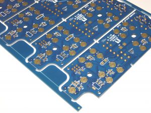
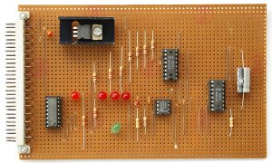
The purpose of circuit board pattern is very critical and practical. Conductive lines are like “roads” on circuit boards, which are responsible for connecting various electronic components so that current can pass smoothly and realize electrical functions. Pads are the “landing points” of components. Pads of different shapes and sizes correspond to different components. For example, the pads of chip capacitors are small and regular, ensuring accurate welding of capacitors.
What is a circuit pattern?
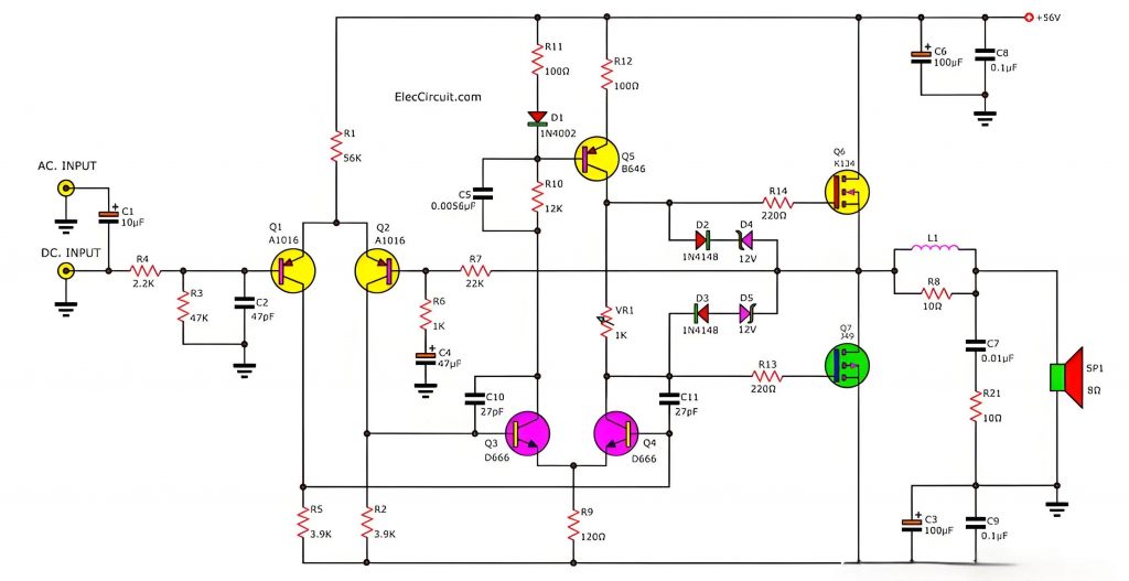
A circuit pattern is a diagram that uses graphic symbols and lines to represent the circuit connection. It is mainly used to reflect the electrical connection and working principle of each component in an electronic device.
Basic components of circuit patterns
- Electronic component symbols: Each electronic component has its own specific symbol to represent the function and characteristics of the component in the circuit. Common electronic component symbols include resistors, capacitors, inductors, diodes, triodes, integrated circuits, etc.
- Connecting wires: used to connect electronic component symbols to indicate the electrical connection between electronic components. In circuit diagrams, connecting wires are usually represented by solid lines to represent the conductive circuit path, and dotted lines to represent control signals or other special connections.
- Power and ground: The power supply is the energy source for the circuit to work, usually represented by a circle or rectangle, with the voltage value and polarity of the power supply marked on it. The ground is the reference potential point in the circuit, usually represented by a triangle or ground symbol.
- Labels and annotations: Used to explain the parameters, models, functions of electronic components and the working principle of the circuit. Labels and annotations can be in words, numbers, symbols, etc.
What are the types of circuit board patterns?
The types of circuit board patterns mainly include the following:
- Schematic diagram: The schematic diagram, also known as the electrical schematic diagram, is a basic drawing that shows the working principle of the electronic circuit. It draws all the components in the circuit and their connection methods in detail, and is an important reference for designing, analyzing and repairing circuits.
- Block diagram: The block diagram is a simplified circuit diagram that uses boxes and wires to represent the main functions and composition of the circuit. It does not show each component in detail, but divides the circuit into several functional modules, each module is represented by a box, and its function is marked.
- Assembly drawing: The assembly drawing is a drawing drawn for the actual assembly of the circuit, which details the position, installation method and connection relationship of each component in the circuit. The symbols on the assembly drawing are usually the physical appearance of the components, which facilitates the actual assembly of the circuit according to the drawings.
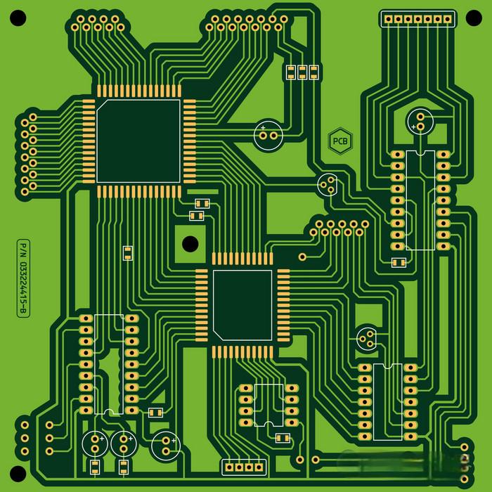
- Printed board drawing: The printed board drawing is also called the printed circuit board drawing or printed circuit board drawing, which shows the layout and connection relationship of the components on the PCB. The symbols and lines on the printed board drawing indicate the connection relationship between the copper foil lines on the PCB and the component pins, ensuring the correctness and reliability of the circuit.
What are the lines on a circuit board for?
The lines on the circuit board are mainly used to connect various electronic components to ensure the normal operation of electronic equipment. Specifically, the lines on the circuit board have the following main functions:
- Connecting electronic components: The lines on the circuit board connect electronic components such as chips, capacitors, resistors, etc. through wires, jumpers, etc. to form a complete circuit, thereby ensuring that the electronic equipment can work properly.
- Power supply and signal transmission: The power supply line is responsible for providing energy to each unit circuit on the circuit board to ensure the normal operation of the equipment. The signal line is used to transmit various signals, such as audio and video signals.
- Grounding and protection: The ground wire is used to ground each electronic component to ensure the safety of electronic products. The protection circuit monitors the operating status of the circuit to prevent abnormal conditions such as overvoltage and overcurrent from damaging the equipment.
- Data and control: Data lines are used to transmit various data, and control lines are used to control various operations of electronic products.
In addition, the design and maintenance of the circuit board are also the key to ensuring the normal function of the circuit. When designing, factors such as the layout, width, number of layers, impedance matching and signal-to-noise ratio of the line need to be considered to ensure the stability and transmission quality of the line.
What is schematic diagram and why is it important in making PCB layout?
A schematic diagram is a diagram that shows the connection relationship between the components in the circuit. It graphically shows the connection relationship and signal flow of the components in the circuit. It is not only a preliminary idea of the circuit design, but also a key reference for subsequent PCB layout and wiring.
The importance of schematic diagrams in PCB layout
- Design basis: The schematic diagram provides the basic framework and connection relationship for PCB design. Designers determine the location of components and the number of layers of the circuit board by analyzing the schematic diagram.
- Quality control: The design quality of the schematic diagram directly affects the quality of the entire project. Accurately understanding the design requirements, selecting appropriate components and verifying them are the keys to ensuring the correctness of the schematic diagram.
- Wiring basis: Schematic diagram is the basis of PCB wiring. By analyzing the schematic diagram, designers can determine the location of components and the layout of the circuit board to ensure smooth signal transmission and avoid problems such as short circuit and open circuit.
- Debugging and maintenance: In the process of product debugging, maintenance and improvement, the schematic diagram plays an indispensable role, helping technicians to quickly locate problems and repair them.
What is the purpose of a PCB layout?
The main purpose of PCB layout is to optimize circuit performance and reduce costs. Specifically, PCB layout involves the reasonable arrangement and connection of electronic components according to the predetermined circuit diagram design to ensure that the physical structure and electrical connection of the circuit board meet the design requirements, thereby ensuring the normal operation and stable performance of the circuit.
How to understand PCB layout?
PCB layout refers to the process of placing electronic components on a printed circuit board (PCB) in a reasonable manner. This process not only involves the arrangement of physical locations, but also requires consideration of electrical performance, manufacturing, and maintenance.
Basic principles and steps of PCB layout
- Schematic diagram analysis: Before PCB layout, you need to understand the schematic diagram and analyze the circuit. This includes distinguishing the circuit according to analog circuits and digital circuits. At the same time, mark out the heat-generating devices and easily interfered devices in the circuit.
- Modular layout: Based on the understanding of the schematic diagram, a modular layout can be established. Select each circuit module and place it in a specific area on the PCB to facilitate subsequent wiring and debugging.
- Signal flow layout: For simple circuits, a signal flow layout can be adopted, usually based on the flow of power signals.
- Center-radiant layout: For complex circuits, especially those involving multiple devices and diverse functions, a center-radiant layout can be adopted, usually with the CPU as the center, and then layout for its peripheral circuits.
Considerations for PCB layout
- Electrical performance: High-frequency components and low-frequency components need to be placed in different areas to avoid mutual interference. The wiring length also needs to be optimized, and shortening the critical signal path can reduce delays.
- Heat dissipation performance: For components with high power and high heat generation, a reasonable layout can provide them with a good heat dissipation channel to prevent components from being damaged due to overheating.
- Manufacturing: A good layout facilitates the installation and welding of components by automated production equipment, improving production efficiency and product quality.
- Maintenance: A clear and organized layout facilitates the later maintenance personnel to quickly locate and replace faulty components, reducing maintenance costs and time.
What is patterning in PCB?
Patterning in PCB is the process of making conductive copper foil into specific patterns and circuits on insulating materials according to the design. The steps are as follows:
- Inner layer production: Clean the copper clad board and apply photosensitive film; stack the copper clad board with PCB layout film, irradiate with UV lamp, clean with alkali solution, etch off the copper foil under the uncured film, and then tear off the film to get the inner layer circuit.
- Hole wall copper plating and outer layer patterning: Chemical deposition on the hole wall and surface copper plating; repeat the pattern transfer and etching steps on the outer layer to form the final conductor pattern.
- Solder mask and silk screen printing: Apply solder mask ink and pattern to protect the circuit and facilitate installation; silk screen printing is used for identification, mostly white or black.
Through these steps, the conductive copper foil is accurately patterned on the insulating material to form a printed circuit board with specific functions and layout.
In short, the circuit board pattern is crucial. Conductive circuits ensure electrical connections and drive components to work together; pads adapt to various components to ensure stable installation; logos and silk screens help workers assemble and maintenance personnel troubleshoot; large areas of copper foil dissipate heat and metallized areas shield electromagnetic interference to maintain stable operation of the circuit board.
Tags: circuit board pattern purpose, PCB


