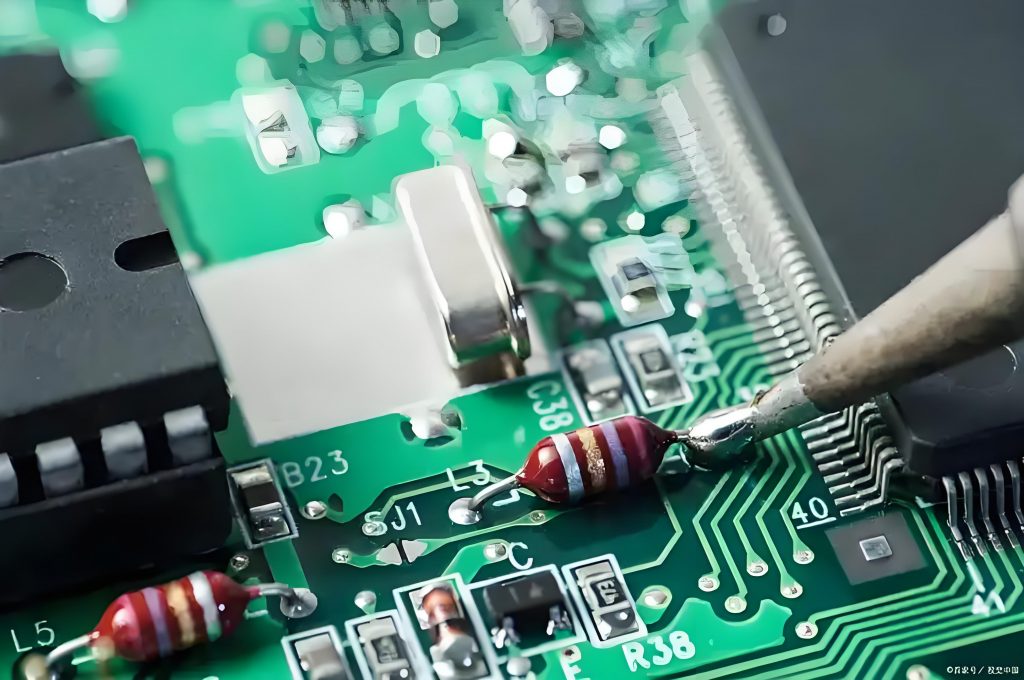
What temp does pc board solder melt? Solder melting points vary depending on the type. Traditional tin-lead solder, the common 63/37 tin-lead alloy melts at about 183°C. Today’s widely used lead-free solder, for example, tin-silver-copper alloy, melts at about 217°C – 227°C. When soldering SMD components, the temperature is set at around 240°C – 260°C to ensure that the tin-silver-copper solder is fully melted.
What temperature do PCBs melt?
The melting point of the PCB substrate itself is usually between 130°C and 140°C. This means that above this temperature range, the FR-4 substrate may begin to soften and melt.
In electronics manufacturing, components on PCB substrates are usually connected by soldering technology. The solder used in the soldering process has a lower melting point, generally between 183°C and 215°C. This ensures that during the soldering process, the solder can melt and form a reliable connection with the PCB substrate and components.
What is the best solder for circuit boards?
The best solder selection for circuit boards depends on the specific application requirements and environmental conditions.
- Tin-lead solder wire: Tin-lead solder wire is one of the most commonly used solders in circuit board soldering. It is usually made of 63/37 tin-lead alloy, which has the advantages of low melting point, good fluidity and easy operation.
- Lead-free solder wire: With the improvement of environmental awareness, lead-free solder wire has gradually become the mainstream. Lead-free solder wire is mainly composed of tin, silver, copper and other elements, and has the characteristics of high melting point, high hardness and wear resistance.
- Silver paste: Silver paste is a packaging material widely used in high-frequency circuits, microwave circuits, power devices and printed circuit boards. It is applied to the surface of the circuit board by spraying or printing, and is baked and cured at high temperature.
What is the melting point of circuit board solder?
The melting point of circuit board solder is usually between 183â and 214â. Commonly used solder is tin-copper alloy, which has good plasticity, conductivity and corrosion resistance, making it the most commonly used soldering material. In addition, the melting point of lead solder is 183â, while the melting point of lead-free solder is 217â.
In the actual soldering process, the soldering temperature is usually about 50â higher than the melting point of the solder, so the actual soldering temperature is generally between 220â and 250â.
For manual soldering, the soldering temperature is generally between 300â and 350â to ensure that the solder wire melts quickly and ensures good wettability. For wave soldering, the optimal temperature is 280â, and the tin furnace temperature can be set to 288±5â.
What temperature does 50/50 solder melt at?
The melting temperature range of 50/50 solder is 190â to 216â. This solder is an alloy composed of 50% tin and 50% lead, and its melting temperature is approximately in this range.
In addition, the melting point of solder varies depending on the composition. For example, the melting points of lead solder wire are as follows:
- 63/37 melting point is 183â
- 60/40 melting point is 185â to 190â
- 55/45 melting point is 187â to 202â
- 50/50 melting point is 190â to 216â
- 45/55 melting point is 192â to 227â
- 40/60 melting point is 194â to 238â
- 35/65 melting point is 198â to 247â
- 30/70 melting point is 202â to 256â.
Can you burn a PCB while soldering?
The PCB may be burned during soldering, which mainly depends on the control of soldering methods and parameters.
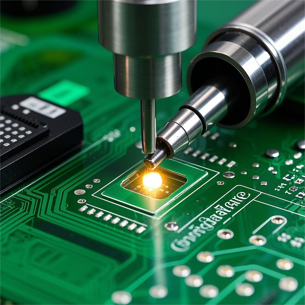
The main reasons for burning PCB during laser welding include:
- Excessive laser power: Laser power is a key factor in determining the heat input of welding. If the power is set too high, the laser energy will be concentrated in the solder joint in a short time, and the heat generated will far exceed the heat required for the solder to melt, causing PCB burns.
- Improper pulse width and frequency: The laser pulse width and frequency will also affect the welding effect. A pulse width that is too long or a frequency that is too high will cause excessive heat accumulation, and the heat transferred to the PCB board will increase, which may cause burns.
- Poor thermal performance of materials: PCB materials have low thermal conductivity or small specific heat capacity, and the heat conduction speed inside the material is slow, which is easy to concentrate near the solder joint, causing local overheating and burns.
- Surface treatment and quality problems: When a PCB board with oil, oxide layer or impurities on the surface is irradiated by laser, the contaminants will absorb part of the laser energy, generate additional heat, and increase the risk of burns.
The reasons for burning PCBs during traditional welding include:
- Excessive welding temperature and excessive welding time: The temperature generated during welding is indeed very high, but if the welding temperature is too high or the welding time is too long, it may cause damage to the components on the circuit board or thermal cracks in the circuit board itself.
Measures to avoid burning PCB
- Choose appropriate welding tools and methods: Choose welding tools that suit your needs and control welding temperature and time. For laser welding, reasonably set the laser power, pulse width and frequency to ensure that the heat input is within a safe range.
- Control welding temperature and time: Set the appropriate welding temperature according to the material of the circuit board and the heat resistance of the components, and try to shorten the welding time.
- Optimize welding skills: Master welding skills to avoid the problems of thermal expansion deformation of copper foil and separation of copper foil from the substrate caused by high-energy local rapid heating.
- Check the quality of PCB boards: Ensure that the surface treatment of PCB boards is clean, without oil, oxide layer or impurities, and avoid contaminants absorbing laser energy to generate additional heat.
What temperature does PCB solder reflow at?
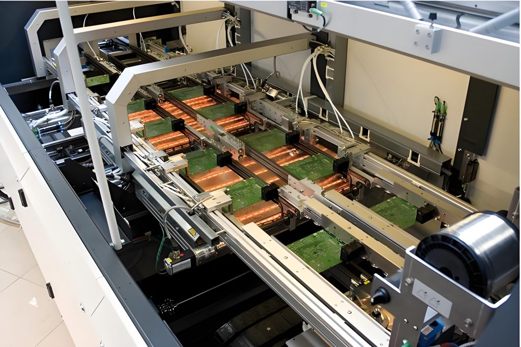
The temperature range of PCB solder during reflow soldering is usually 220â to 249â. During the reflow soldering process, the solder paste needs to undergo processes such as solvent volatilization, flux removal of oxides on the surface of the weldment, solder paste melting, reflow, and solder paste cooling and solidification. The specific temperature zones are as follows:
- Preheating zone: The temperature gradually rises from room temperature to about 150â. At this stage, the solvent and gas in the solder paste begin to evaporate, the flux wets the pads and component pins, and the softened solder paste covers the pads, isolating oxygen and preparing for the next welding.
- Constant temperature zone: The temperature is between 150â and 200â, ensuring that the PCB and components are fully preheated to avoid damage to the PCB and components due to a sudden temperature rise.
- Reflow zone: The temperature rises rapidly to 220â, up to 249â. In this area, the solder paste reaches a molten state, the liquid solder wets and diffuses, and forms solder joints between the pads, component ends and pins.
- Cooling zone: The solder joints gradually solidify, completing the entire reflow process.
Temperature control during reflow is extremely important because it directly affects the welding quality and product reliability. Too high or too low temperature may cause welding defects such as solder balls, cold soldering, bridging and other problems.
What temperature should pcb be desoldered at?
The temperature range of PCB during desoldering is generally between 250â and 350â. The specific temperature should be adjusted according to the size and type of components on the circuit board. For smaller components and thin lines, the temperature should be set at around 250â; for larger components and thicker solder joints, the temperature can be set at around 350â.
Specific temperature requirements for different welding methods
- Manual welding: usually set between 300â and 350â. For precision components such as IC and SMD, it is recommended to control between 260â and 300â; for welding of large-area heat sinks or power lines, the temperature may need to be increased to around 380â.
- Wave soldering: The temperature of the preheating zone is usually 90â to 140â, and the temperature of the solder tank is 240â to 260â.
- Reflow soldering: The temperature of the preheating zone is 150â to 200â, the wetting zone is maintained at 150â to 200â, the temperature of the reflow zone is 230â to 260â, and the temperature of the cooling zone drops rapidly to below 100â.
- Laser welding: The local temperature is usually 250â to 300â, and the exposure time is usually 0.1 to 2 seconds.
In short, the melting point of printed circuit board solder varies depending on the type and application scenario. Among traditional tin-lead solders, the melting point of 63/37 tin-lead alloy is about 183â, which was widely used in PCB welding. With the demand for environmental protection, lead-free solder has emerged, and the melting point of common tin-silver-copper alloy is 217â – 227â.


