What is Diode Polarity?
Diode polarity refers to the direction in which a diode allows electrical current to flow. Every diode has two terminals: the anode (positive side) and the cathode (negative side). When the anode is connected to a higher voltage than the cathode, the diode is forward biased, allowing current to pass through. However, if the cathode is at a higher voltage than the anode, the diode becomes reverse biased, blocking current flow.
Diodes serve various purposes in circuits, including rectification, voltage regulation, and circuit protection. Their ability to control current flow makes them essential in electronics. Misplacing a diode in a circuit may cause malfunction or even damage components. Recognizing diode polarity ensures correct installation and prevents unnecessary failures.
Diode Polarity Diagram
A diode polarity diagram visually represents the direction in which current flows. This is especially useful when assembling circuits, as placing a diode incorrectly can prevent it from functioning as expected.
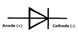
A diode symbol consists of a triangle pointing toward a vertical bar:
- The triangle represents the anode.
- The vertical bar represents the cathode.
- The arrow direction indicates the forward current flow.
When placed in a circuit, current moves from the anode to the cathode. If the diode is reversed, it blocks the current. Some circuits use multiple diodes to form rectifiers, which convert alternating current (AC) into direct current (DC).
Diode Polarity Symbol
The diode polarity symbol is a crucial element in circuit diagrams. It consists of a triangle pointing towards a line, which indicates the anode and cathode, respectively. The direction of the triangle’s tip represents allowed current flow under forward bias conditions.
Different types of diodes have unique symbols:
- Standard diodes follow the common triangle-line symbol.
- Zener diodes include additional markings to show reverse conduction properties.

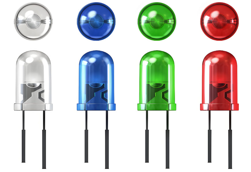
- Light-emitting diodes (LEDs) feature arrows pointing outward to indicate light emission.

- Schottky diodes may have a bent line to differentiate them from standard diodes.
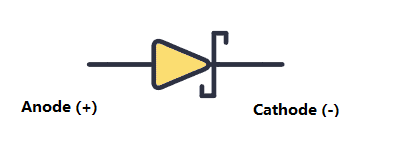
Recognizing these symbols is essential when reading circuit schematics, as incorrect placement can lead to non-functioning circuits.
Diode Polarity Marking on PCB
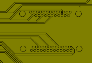
Printed circuit boards (PCBs) often include polarity markings to indicate diode orientation. These markings prevent assembly errors and ensure the circuit functions correctly.

How to Identify Polarity on a PCB?
Manufacturers use different methods to show diode polarity on PCBs:
- Stripe on the Cathode Side â Most diodes have a silver, white, or black stripe near the cathode. This matches the bar in the schematic symbol.
- “+” or “-” Symbols â Some PCBs label the anode with a “+” sign and the cathode with a “-“.
- Silkscreen Markings â The PCB itself may include a diode symbol, with a triangle and line, showing the correct orientation.
Before soldering a diode, itâs best to check the PCB layout or schematic. Placing a diode backward could cause circuit failure or prevent power from reaching essential components.
How Do You Know the Polarity of a Diode?
There are several ways to determine a diode’s polarity:
- Look for the Cathode Stripe â Most diodes have a stripe marking the cathode.
- Check the PCB Markings â The silkscreen design often includes polarity symbols.
- Use a Multimeter â Setting a multimeter to diode test mode can quickly confirm polarity. When the positive probe touches the anode, a small voltage drop appears, indicating correct polarity. Reversing the probes results in no reading.
Using these methods helps confirm proper orientation before placing a diode into a circuit.
Does Diode Polarity Matter?
Yes, diode polarity is critical for proper circuit operation. Diodes only allow current to move in one direction, so incorrect placement leads to non-functioning circuits or even damage.
Some applications, like Zener voltage regulators, rely on reverse bias operation. However, in standard circuits, always check the polarity before installation.
What Happens When You Reverse the Polarity of a Diode?
If a diode is accidentally reversed, its effect depends on the circuit:
- In Series with a Load â No current flows, and the circuit may not function.
- In a Rectifier Circuit â The AC-to-DC conversion fails, possibly causing incorrect voltages.
- In a Protection Circuit â Reverse polarity protection diodes conduct and may blow a fuse to prevent damage.
Reversing a diode generally blocks current, but Zener diodes and certain specialized diodes can operate in reverse bias under controlled conditions.
Does a Diode Convert AC to DC?
Yes, diodes are key components in AC-to-DC conversion. This process, called rectification, involves blocking the negative part of an AC signal, allowing only positive current flow.
There are different rectifier configurations:
- Half-Wave Rectifier â Uses a single diode to remove the negative cycle.
- Full-Wave Rectifier â Uses four diodes (bridge rectifier) to convert the entire AC waveform to DC.
A rectifier circuit is often combined with capacitors to smooth the output, resulting in stable DC power.
What is the Output if the Diode is Reversed?
If a diode is installed backward, the output depends on the circuit type:
- In a Power Supply â The circuit may stop working due to lack of current flow.
- In a Rectifier â AC may pass through without being converted, leading to unstable output.
- In a Protection Circuit â The reverse diode may conduct, causing a fuse to blow.
Checking orientation before soldering prevents these issues and ensures proper function.
How Do You Protect Reverse Polarity with a Diode?
Reverse polarity protection prevents damage when power is connected incorrectly. There are two common methods using diodes:
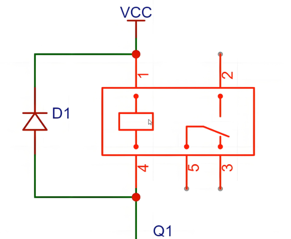
- Series Diode Protection â A diode is placed in series with the power supply. If polarity is incorrect, the diode blocks current, preventing damage.
- Parallel Diode with Fuse â A diode is placed in parallel across the power rails. If polarity is reversed, the diode conducts, causing a fuse to blow and protecting sensitive components.
Both methods are effective, though the series method introduces a slight voltage drop, while the parallel method requires a replaceable fuse.
How to Determine If a Diode is Forward or Reverse Biased?
A diodeâs biasing state depends on voltage conditions:
- Forward Bias â The anode is at a higher voltage than the cathode, allowing current to flow.
- Reverse Bias â The cathode is more positive than the anode, blocking current.
To check bias, use a multimeter in voltage mode. A forward-biased diode typically shows a voltage drop of:
- 0.7V for Silicon Diodes
- 0.3V for Germanium Diodes
Reverse bias shows no voltage drop, indicating no conduction.
Can You Test Polarity with a Multimeter?
Yes, a multimeter in diode mode is the easiest way to test polarity:
- Place the red probe on one terminal and the black probe on the other.
- Check the reading:
- A reading means the red probe is on the anode and the black probe is on the cathode.
- No reading means the diode is reversed.
- Reverse the probes to confirm. A functional diode only conducts in one direction.
In a word, misplacing a diode can prevent a circuit from working or even cause damage. Learning check polarity markings, using multimeter tests, and understanding circuit symbols ensure correct installation. If you have more questions about diode polarity or diode assembly in PCB, just feel freely to contact us, we are always online!


