
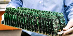
PCB board stands for Printed Circuit Board, a vital component used in nearly all electronic devices. It serves as the backbone for connecting various electronic components, such as resistors, capacitors, and microchips, to ensure they work together efficiently. The PCB acts as a physical support and an electrical connection for these components. Understanding how a PCB board functions, its design process, and its costs can help manufacturers and engineers when creating new devices or products.
In this article, we will dive into the essential aspects of PCB boards, from their design and creation to maintenance and testing. We’ll also explore their various types, materials, and how much they cost, helping you make informed decisions whether you’re designing your own circuit board or sourcing from PCB board manufacturers.
What Does a PCB Stand For?
PCB stands for Printed Circuit Board. It is a flat, non-conductive material that supports and connects electronic components via conductive pathways etched or printed onto the board. These pathways, often made of copper, form the electrical circuits that allow devices to function. PCBs come in various shapes and sizes, depending on the complexity and requirements of the devices they support. They’re found in everything from smartphones to household appliances and even in large industrial machines. Understanding the definition and the purpose of a PCB board is essential before diving into its design and creation process.
How to Design a PCB Board?
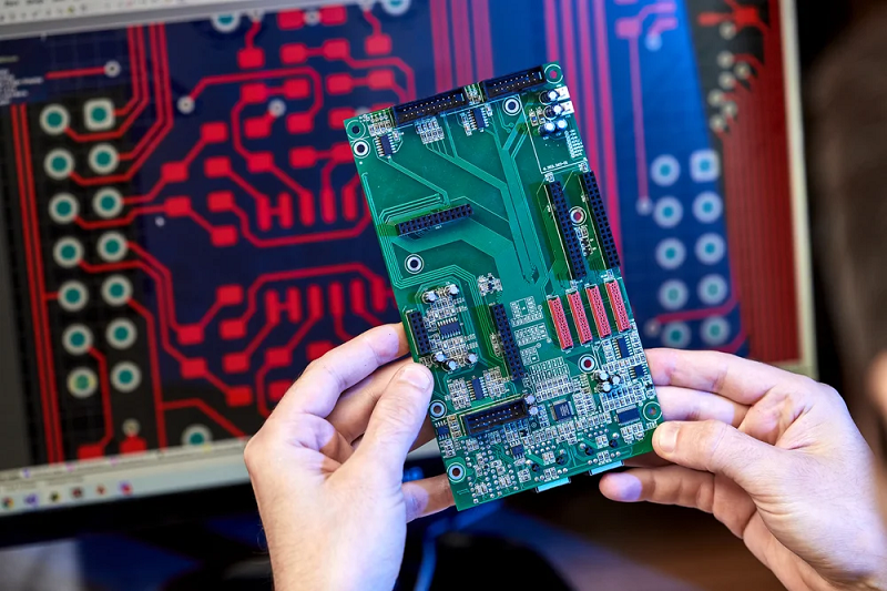
Designing a PCB board begins with understanding the circuit requirements. The design process typically involves several stages:
Schematic Design: This is the initial stage where the electrical components are selected, and the circuit is drawn.
PCB Layout: In this stage, the physical layout of the components on the board is planned, considering space, component size, and heat dissipation.
Routing: The routing phase involves laying down copper traces to connect components.
Verification: A thorough review and testing phase to ensure that the design works as intended.
For a successful PCB board design, it is essential to use specialized software tools like Eagle, Altium Designer, or KiCad. These programs allow for detailed and precise layout planning.
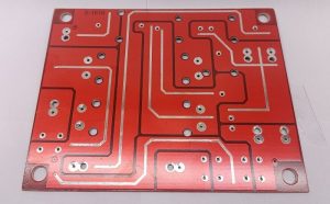
How to Make a PCB Board?
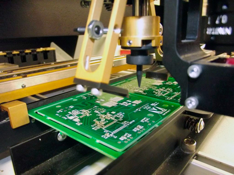
Making a PCB board requires several steps, which involve both manual and machine processes. Here’s a basic overview:
Create the PCB Design: First, design the PCB using software.
Print the Design: Once the design is ready, print it onto a copper-coated board.
Etch the Board: Use chemicals to remove unwanted copper, leaving behind the circuit design.
Drill Holes: If necessary, drill holes for components like resistors and capacitors.
Apply Soldermask and Silkscreen: These layers protect the copper traces and display component information, respectively.
Solder Components: Finally, solder the components into place.
This process can be done in-house with the right equipment or outsourced to professional printed circuit board manufacturers.
How to Clean a PCB Board?
Cleaning a PCB board is important to ensure it remains free of dust, oils, and other contaminants that could impact its performance. To clean your PCB:
Use Isopropyl Alcohol: Apply a small amount of isopropyl alcohol (preferably 99%) to a soft brush or cloth.
Gently Scrub the Board: Lightly scrub the surface to remove dirt or residue.
Dry the Board: After cleaning, let the board dry completely before use.
Always avoid using abrasive materials that could damage the surface of the PCB.
How to Solder Wire to PCB Board?
Soldering wires to a PCB board requires precision. Here’s how to do it:
Prepare the Tools: You’ll need a soldering iron, solder, flux, and wire.
Apply Flux: Lightly apply flux to the pads where the wire will be soldered.
Heat the Soldering Iron: Heat the soldering iron to around 350°C.
Solder the Wire: Place the wire on the pad and apply the solder to the joint. Remove the soldering iron and let the joint cool.
Proper soldering ensures a solid, reliable connection.
How to Cut a PCB Board?
Cutting a PCB board is a simple task but requires care to avoid damaging the board. Here’s how to do it:
Mark the Cutting Line: Use a pencil or marker to draw a straight line where you want to cut.
Use a PCB Cutter or Dremel: A specialized PCB cutter or Dremel tool with a cutting disk is ideal for clean, straight cuts.
Smooth the Edges: After cutting, use a file to smooth any rough edges.
Cutting the PCB allows it to fit into specific devices or designs. Always wear protective gear while cutting.
How to Test a PCB Board?
Testing a PCB board involves checking its electrical functionality. You can use several methods:
Visual Inspection: Look for any obvious issues, such as broken traces, soldering issues, or misplaced components.
Functional Testing: Power the circuit and verify if the board operates as expected.
Automated Testing Equipment (ATE): High-tech equipment can test multiple points on the PCB simultaneously.
Testing ensures the PCB performs correctly and meets quality standards.
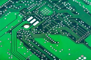
How to Read a PCB Board?
Reading a PCB board involves interpreting the layout and understanding the component functions. You should:
Identify Components: Look for the labels next to the components, which should indicate their type (e.g., R for resistors, C for capacitors).
Understand the Traces: Follow the copper traces to understand how power and signals flow between components.
Check for Connections: Ensure that the components are properly connected, with no short circuits or unconnected pads.
Reading a PCB board is crucial when troubleshooting or making modifications.
How to Check a PCB Board with Multimeter?
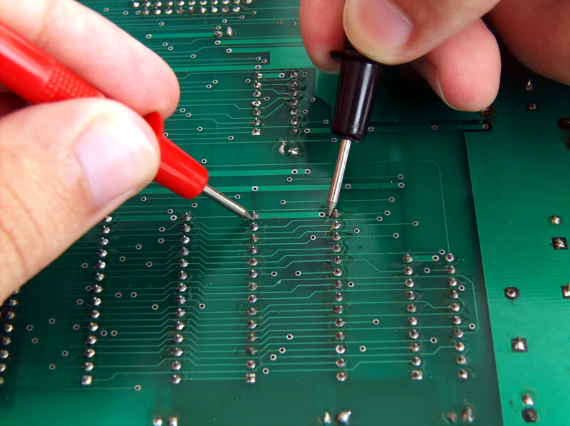
A multimeter is a valuable tool for checking a PCB board. Here’s how you can use it:
Set the Multimeter to Continuity Mode: This will allow you to test whether there are any open circuits.
Check the Connections: Place the multimeter probes on two points that should be connected, and verify continuity.
Measure Resistance: Check for components that should have specific resistance values to ensure they are working correctly.
Regular checks with a multimeter can help ensure the PCB board’s functionality and durability.
How Much Does a PCB Board Cost?
The cost of a PCB board varies. Simple prototypes start around $5–$50 each. Bulk orders drop prices to $0.10–$10 per board. Key factors
Size/Layers: Bigger or multi-layer boards cost more
Material: Standard FR-4 is cheaper; special materials (flexible, high-frequency) add cost.
Quantity: Higher volume = lower per-unit price.
Turnaround: Faster delivery increases cost.
Looking for an accurate quote? Share your specifications on our website for fast and competitive pricing!
In conclusion, PCB boards are the foundation of modern electronics, connecting components and ensuring devices function smoothly. Understanding their design, manufacturing, and maintenance is crucial for anyone working with electronics. Whether you’re designing a PCB board, testing its functionality, or sourcing from printed circuit board manufacturers, having the right knowledge can make all the difference.
Best Technology has over 18 years of experience in the PCB industry, providing top-quality PCBs for a variety of applications. We offer a range of materials and services to meet your specific needs, ensuring you receive reliable and cost-effective solutions. For details or inquiries, feel free to contact us at sales@bestpcbs.com.
You may also like


Tags: PCB, PCB Board, pcb design, printed circuit board