
Impedance controlled PCB for medical device is a circuit board that ensures signal integrity and stability by precisely controlling the characteristic impedance of PCB traces. It is used in medical equipment to process weak bioelectric signals or high-frequency signals, such as electrocardiographs, ultrasonic diagnostic equipment, etc., to reduce signal reflection and interference and improve the accuracy of diagnosis and treatment.
What is controlled impedance in pcb?
Impedance control in PCB refers to the practice of ensuring the resistance to alternating current (AC) is consistent across the entire PCB. This resistance is known as impedance, and controlling it means that the PCB will behave predictably when transmitting signals, especially at high frequencies.
The primary goal of impedance control is to maintain signal integrity, ensuring that signals are transmitted without distortion or reflection, which can lead to errors and system failure.
For medical devices, where accuracy is paramount, maintaining controlled impedance is vital for reliable operation.
Whether for analog signals in imaging equipment, digital signals in diagnostic tools, or communication signals in wearable health devices, impedance mismatches can cause disruptions, leading to inaccurate readings or device malfunction.
What is the standard impedance of a pcb?
The standard impedance of a PCB is typically defined as either 50 ohms or 75 ohms, depending on the design requirements.
50-ohm impedance is commonly used for high-speed signal transmission, such as in RF circuits, while 75-ohm impedance is used for applications requiring high-frequency signal transmission, like video equipment.
For controlled impedance PCBs, the value of impedance can be tailored based on the application. Impedance values are calculated during the design phase, and various factors such as trace width, trace spacing, and PCB material are taken into consideration.
Why is impedance matching important in pcb?
Impedance matching is essential in any electronic circuit, but it is even more crucial in high-frequency applications such as medical devices.
Without proper impedance matching, signal reflections can occur, which can distort the signal and cause errors. This can severely impact the performance of a medical device, where precise signal transmission is needed to provide accurate data.
Signal integrity is critical when dealing with devices like ECG machines, MRI scanners, and hearing aids. When impedance is matched correctly, signals travel with minimal distortion, allowing the device to operate optimally and produce reliable data.
When does a pcb require impedance control?
Impedance control becomes necessary when a PCB handles high-speed signals, such as in RF circuits, communications, and data transmission.
Medical devices like imaging equipment, patient monitoring systems, and wearable health devices often fall into this category due to the need for high-speed data processing and communication.
In general, impedance control should be used whenever a circuit requires:
- High-frequency operation (above 100 MHz)
- High-speed signal integrity
- Minimized noise or crosstalk between signal lines
If your device involves analog or digital signal processing, especially in an environment where accuracy is critical, impedance control is vital.
What are the factors affecting impedance in pcb?
Impedance control in PCB design involves careful calculation and consideration of the following factors:
- Trace Width: The width of the signal traces directly affects impedance. Wider traces lower impedance, while narrower traces increase it.
- Trace Spacing: The space between signal traces also affects impedance. The closer the traces, the lower the impedance, and the wider the separation, the higher the impedance.
- PCB Material: The dielectric constant of the PCB material plays a significant role in impedance control. Materials like FR4 or specialized materials with lower dielectric constants are often used for controlled impedance designs.
- Trace Length: Long traces can cause signal delay and reflection. By limiting the length or controlling the impedance over the entire trace, you can ensure signal integrity.
- Ground and Power Planes: Well-designed ground and power planes reduce noise and minimize the risk of impedance mismatch by providing a stable reference.
How does impedance affect signal quality?
Impedance mismatch can cause signal reflections, attenuation, and distortion.
In PCB design, mismatched impedance leads to data loss, slower transmission speeds, and errors in signal interpretation. This can have serious implications in medical devices where accurate and real-time data transmission is critical.
In particular, RF circuits in medical devices rely heavily on impedance control. If the impedance is not matched correctly, it could cause errors in data processing, affecting everything from patient monitoring to diagnostic imaging.
How do you avoid high-frequency interference in pcb?
To avoid high-frequency interference (EMI or electromagnetic interference) in impedance controlled PCBs, several steps can be taken:
- Careful Routing: Ensure traces are short and direct. Avoid sharp bends and keep signal paths as clean as possible.
- Ground and Power Planes: Well-planned and solid ground planes reduce noise and minimize interference.
- Shielding: Use shielding materials to contain signals and prevent them from radiating interference.
- Signal Trace Spacing: Keep sensitive signal traces apart to reduce crosstalk and interference between them.
- Use of Ferrite Beads or Filters: These can help reduce high-frequency noise in specific sections of the PCB.
For medical devices, it’s crucial to follow these steps to prevent interference that could lead to inaccurate readings or signal loss.
What are the applications of controlled impedance pcb?
Impedance controlled PCBs have broad applications in medical devices and other high-frequency technologies. Some key uses include:
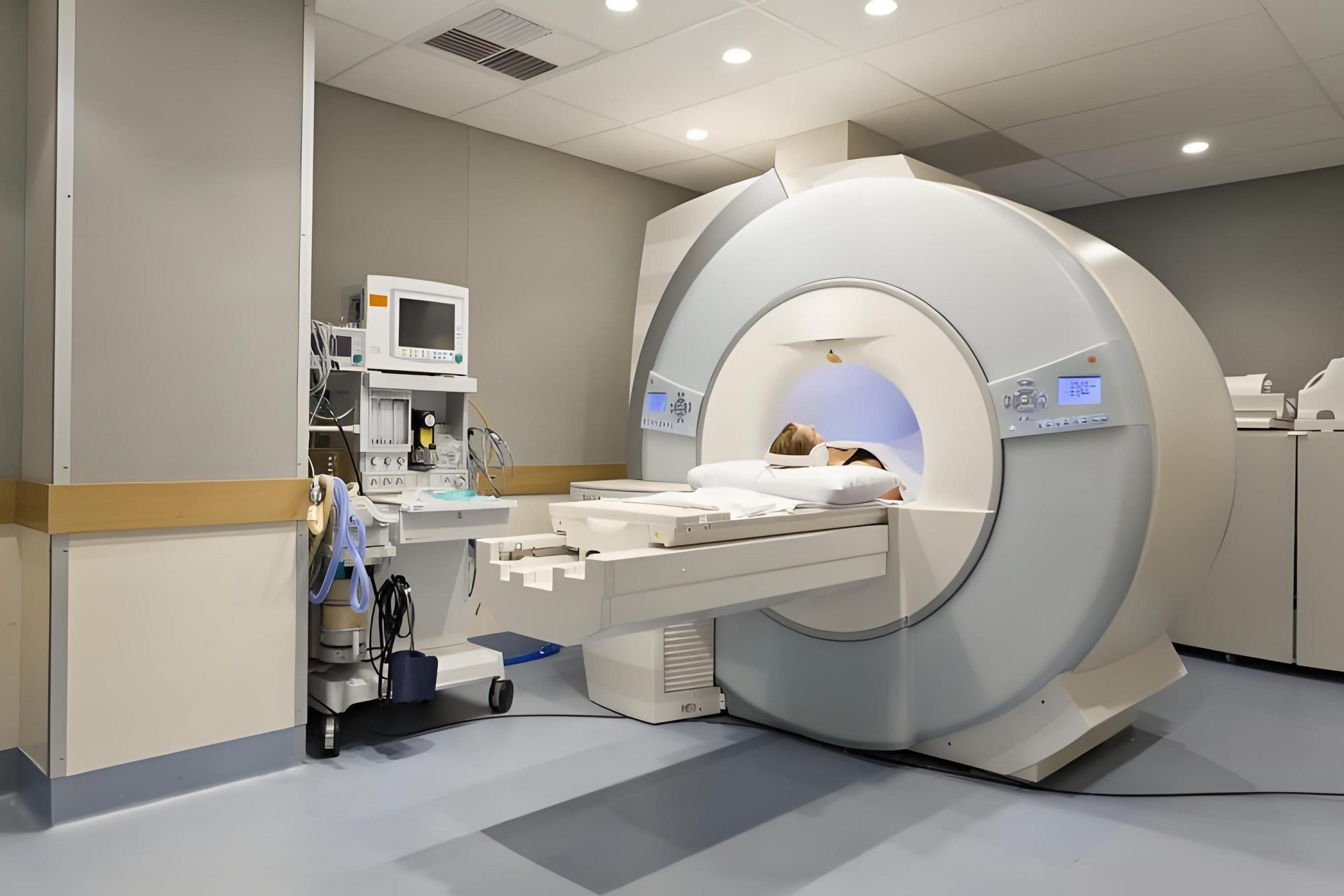
- Medical Imaging Devices: Accurate data transmission is needed in MRI, CT scanners, and ultrasound systems, where high-frequency signals are common.
- Wearable Medical Devices: Devices such as heart rate monitors, smartwatches, and glucose monitors rely on impedance-controlled PCBs to ensure stable signal quality over Bluetooth or Wi-Fi.
- Patient Monitoring Systems: Continuous data transmission in these systems requires accurate, low-noise signals to maintain the health and safety of the patient.
- Diagnostic Equipment: Impedance-controlled designs are critical in devices used for blood analysis, ECG/EKG, and other diagnostic purposes that need to maintain the integrity of analog signals.
Conclusion:
When designing printed circuit boards for medical devices, ensuring high signal integrity is critical. One of the most important aspects of achieving this is impedance control.
If you’re looking for high-quality, impedance-controlled PCBs for medical devices, Best Technology is your trusted partner. Contact us at sales@bestpcbs.com to learn more.
You may also like


Tags: control impedance in pcb, impedance control in pcb, impedance control pcb