

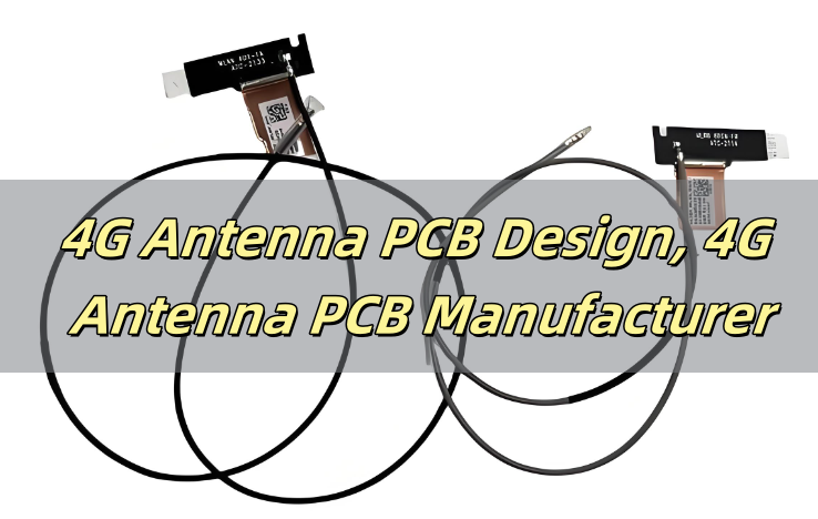
What is a 4G Antenna PCB?
A 4G antenna PCB is a printed circuit board with an integrated antenna designed to support 4G LTE communication. It features in converting electrical signals into radio waves, enabling stable and efficient wireless communication. Unlike traditional external antennas, PCB antennas are compact, cost-effective, and easily integrated into various devices.
These antennas are widely used in smartphones, IoT devices, routers, industrial automation systems, and automotive applications. Since they are directly embedded into the PCB, they eliminate the need for extra external components, reducing design complexity while enhancing performance. A 4G antenna typically consists of the following components:
- Antenna: Responsible for receiving and transmitting wireless signals.
- Baseband Chip: Handles signal encoding and decoding, as well as data modulation and demodulation.
- RF Front-End Chip: Amplifies and filters wireless signals to ensure signal quality and stability.
- Power Management Unit (PMU): Supplies power to the module and manages voltage conversion.
- Digital Signal Processing Unit (DSP): Integrated within the baseband chip, responsible for digital signal processing.
- Memory: Includes NAND FLASH and DDR SDRAM for storing firmware and temporary data.
Where Can I Find a Reliable 4G Antenna PCB Manufacturer?
Choosing a reliable manufacturer ensures a high-quality 4G antenna PCB. Look for:
- Expertise in RF PCB Design
- Advanced Manufacturing Techniques
- Custom Design Support
- Strict Quality Control Certifications
Best Technology specializes in manufacturing high-performance RF and antenna PCBs with over 18 years of experience. We have passed ISO9001, IATF16949, ISO13485, AS9100D certifications, give you a strictly quality control assurance. In addition to this, 80% of our engineers are engaging in PCB design & manufacturing for more than 10 years, they are experts in this industry and enable to give you a best solution tailored to your requirements. Our advanced production process ensures top-quality PCB antennas for IoT, telecommunication, and industrial applications.
Characteristics of a 4G Antenna PCB
A well-designed 4G antenna PCB exhibits several essential characteristics:
- Frequency Range and Band Optimization
4G antenna PCBs typically cover a frequency range from LTE 600MHz to 60,000MHz, ensuring compatibility with all 4G and 5G frequency bands. These antennas are optimized to deliver stable performance across multiple communication spectrums.
- High Efficiency
For all 4G and CBRS bands, the efficiency of 4G antenna PCBs exceeds 50%, ensuring strong and reliable signal transmission.
- Materials and Design
Special substrate materials with high dielectric constants or low loss tangents are used to enhance antenna efficiency and minimize energy loss. Additionally, advanced plating techniques improve the conductivity and corrosion resistance of copper foil, further enhancing durability and signal transmission quality.
- Structural Optimization
Using 3D modeling software, antenna structures are precisely simulated and optimized. Adjustments to the shape, size, and layout of radiating elements help refine radiation patterns, gain, and bandwidth.
- Integration Technology
Key RF components such as filters, couplers, and switches are directly integrated into the PCB antenna, creating an all-in-one solution that reduces signal loss caused by external connections.
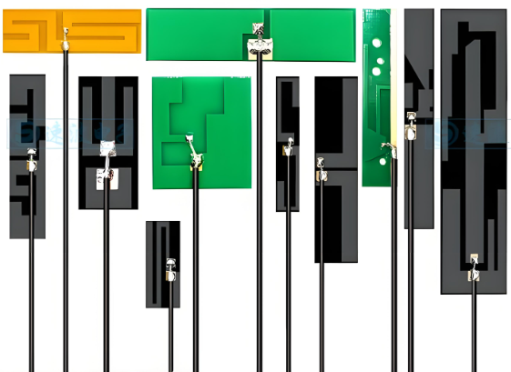
Types of 4G Antenna PCB
The main types of 4G antenna PCBs include the following:
Internal Antennas
Internal antennas are usually integrated into mobile phones, tablets, and other terminal devices. They offer a high level of integration and an aesthetically pleasing design, though their performance is slightly lower compared to external antennas. Internal antennas include PCB trace antennas and FPC antennas.
- PCB Trace Antenna
This type of antenna is directly laid out on the PCB circuit board as a conductor. It is suitable for single-band module circuit boards, such as Bluetooth modules, Wi-Fi modules, and Zigbee modules. The main advantages are that it incurs no additional cost and requires no further tuning after initial calibration. However, it is only suitable for single-frequency applications.
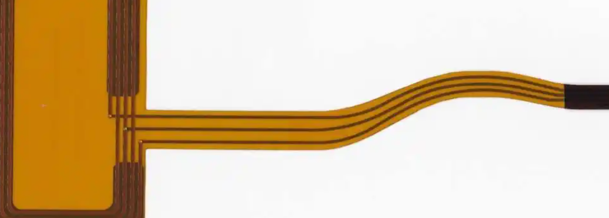
- FPC Antenna
An FPC antenna extends the antenna circuitry from the PCB board and uses external metal materials to form the antenna. It is commonly used in mid-range and low-end mobile phones as well as smart hardware products with complex frequency requirements.
External Antennas
External antennas are installed on surfaces such as buildings or vehicles to enhance signal reception and transmission. They typically offer superior performance and broader signal coverage.
- Patch Antenna
Patch antennas are compact, providing moderate performance and cost-effectiveness. They are suitable for devices that require a miniaturized design.
- External Whip Antenna
Whip antennas are larger in size and offer high performance but come at a higher cost. They are used in applications that demand strong signal transmission capabilities.
Working Principle of a 4G Antenna
The working principle of a 4G antenna mainly involves the process of receiving and transmitting wireless signals. As a crucial part of the 4G module, the antenna is responsible for handling wireless signals to enable high-speed data transmission and communication. Its working process are:
- Signal Reception: The 4G antenna receives wireless signals firstly from the base station and transmits them to the baseband chip for processing.
- Signal Processing: Then the baseband chip decodes and demodulates the received signal, then transfers the processed data to other devices or networks.
- Signal Transmission: Next, data generated by the device or application is encoded and modulated by the baseband chip, amplified and filtered by the RF front-end chip, and finally transmitted via the antenna.
Why Does 4G Need Two Antennas?
4G devices use two antennas to get better signal strength, faster speeds, and a more stable connection. This technology is called MIMO (Multiple Input Multiple Output) and helps improve how data is sent and received. By using this technology, the device enables to achieve:
1. Stronger Signal – With two antennas, the device can pick up signals from different directions.
2. Faster Internet Speeds – Two antennas allow the device to send and receive more data at the same time, so users download and upload much faster.
3. More Stable Connection- If one antenna gets a weak signal due to interference or obstacles, the second antenna can still keep the connection steady.
4. Less Delay (Lower Latency) – A dual-antenna setup reduces lag, making activities like video calls, gaming, and streaming smoother with fewer interruptions.
5. Handles More Network Traffic – With two antennas, data moves more efficiently, preventing slowdowns when many people are using the network at the same time.
Simply put, 4G needs two antennas to make internet connections faster, stronger, and more reliable, so users get a better experience wherever they are.
What Cable is Used for a 4G Antenna?
A coaxial cable is commonly used to connect 4G antennas. The best options include:
- RG58: Suitable for short-range applications.
- RG174: A thinner cable ideal for compact designs.
- LMR400: Low-loss cable for long-distance connections.
Does 4G and 5G Use the Same Antenna?
No, 4G and 5G use different antenna with different frequency bands.
- 4G Antennas: Operate in frequencies from 700 MHz to 2.7 GHz.
- 5G Antennas: Use higher frequencies, including millimeter waves (24 GHz to 100 GHz).
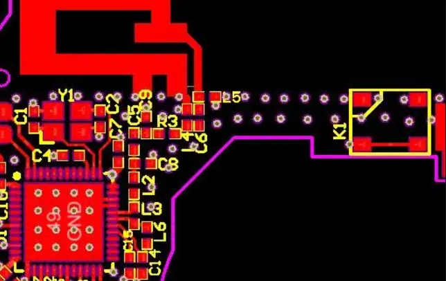
4G LTE Antenna PCB Design and Layout Rules
1. Maintain Proper Ground Plane Design
- Use a large, continuous ground plane: A larger ground area improves signal stability and radiation efficiency.
- Avoid ground plane interruptions: Any cut or split in the ground plane can create unwanted parasitic capacitance and affect the antenna’s impedance matching.
- Ensure proper grounding of RF components: Connect the antenna’s ground to a low-impedance ground plane for better signal integrity.
2. Optimize Trace Width and Length
- Keep RF traces as short as possible: Long traces increase resistance and reduce efficiency.
- Use controlled impedance traces: Maintain a 50-ohm characteristic impedance for minimal reflection and signal loss.
- Avoid sharp bends in traces: Use curved or chamfered traces instead of 90-degree angles to prevent signal reflection.
3. Place the Antenna in an Unobstructed Area
Keep the antenna at the board edge or corner, avoid placing the antenna near high-speed signals or power components.
4. Maintain Proper Antenna Clearance
Leave at least 5mm to 10mm of clearance around the antenna for best performance. Do not place the antenna too close to the battery or shielding can, as these components absorb and distort signals. For multi-layer PCBs, ensure no traces run directly under the antenna to avoid unwanted coupling effects.
5. Use Proper Via Design for RF Signals
Vias in RF circuits can cause signal loss and interference if not used correctly. Minimize via transitions in RF traces because Excessive vias create unwanted inductance. If vias are required, use multiple vias in parallel is good to maintain signal continuity.
6. Follow Proper Antenna Matching Techniques
Use a matching network (capacitors and inductors) to fine-tune the antenna to 50-ohm impedance.
7. Consider the PCB Material and Stack-up
Use low-loss PCB materials like Rogers 4350B or FR4 for high-frequency applications. For multi-layer PCBs, separate RF traces from power and signal layers to minimize interference.
8. Prevent Electromagnetic Interference (EMI)
4G antennas PCB design can suffer from EMI due to switching power supplies, digital signals, or nearby RF components. Use shielding techniques like grounded enclosures for noise reduction.
9. Simulate Before Manufacturing
Before finalizing the design, simulate the PCB layout using RF design software like CST Studio Suite, HFSS, or ADS to analyze antenna radiation patterns and impedance matching.
FAQs
1. Can I use a Wi-Fi antenna for 4G?
No, Wi-Fi and 4G antennas operate on different frequency bands.
2. How do I test my 4G antenna PCB?
Use network analyzers to measure impedance matching, return loss, and radiation pattern.
3. What is the ideal thickness for a 4G antenna PCB?
It varies, but common thicknesses range from 0.8mm to 1.6mm.
4. Do I need an amplifier for my 4G antenna?
Only if you need to boost weak signals in long-distance applications.
5. Can I use a flexible PCB for a 4G antenna?
Yes, flexible PCBs are ideal for wearables and compact devices.
Tags: 4g antenna pcb lte