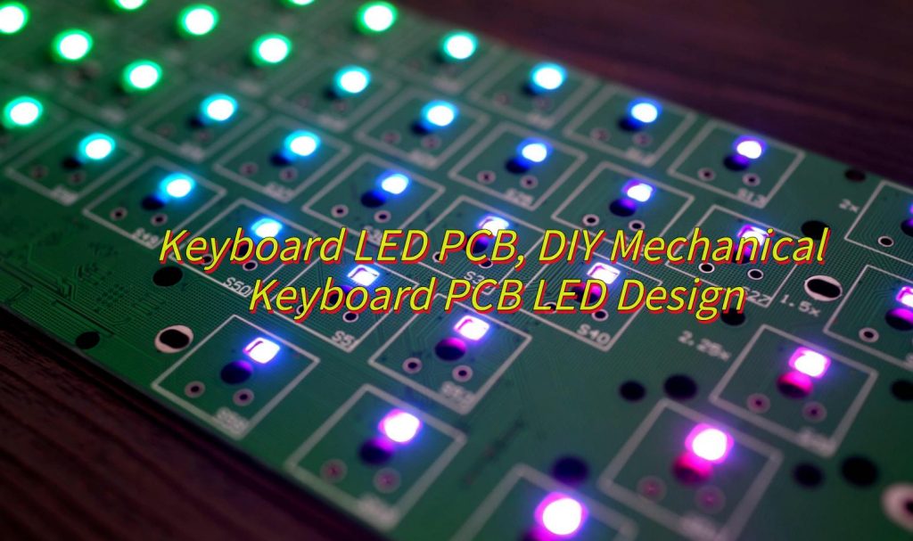
Would you like to know how to DIY a keyboard LED PCB? This blog covers everything from DIY PCB layouts and RGB effects to polarity checks and troubleshooting, ensuring a seamless path from prototype to production.
EBest Circuit (Best Technology) specializes in keyboard LED PCB solutions, delivering strict IP protection (NDA agreements and encrypted R&D processes), proven 8×16 RGB matrix technology (refresh rates â„200Hz, current control within ±5%), and modular designs. Our aluminum substrates and QMK/VIA-compatible firmware ensure thermal stability and ultra-low latency (<3ms), while high-reflectivity materials reduce power consumption by 15-20%. Supported by a 24/7 multi-engineer team offering free design technical support, integrated DFM analysis, and EMC testing, we promise one-time prototyping success. If you have any request in keyboard LED PCB, please feel free to contact us: sales@bestpcbs.com
What Is AÂ Keyboard LED PCB?
A Keyboard LED PCB is a specialized printed circuit board designed for mechanical keyboards, integrating both signal transmission and LED backlight control. Typically constructed with a metal core, such as aluminum, it efficiently dissipates heat generated by prolonged LED use while ensuring durability. Conductive copper traces on the board connect mechanical switches to LEDs, enabling real-time input signaling and customizable RGB lighting effects via embedded microcontrollers. Advanced designs may support multi-layer layouts for complex RGB configurations, software-driven light customization, and thermal management through materials like aluminum substrates.

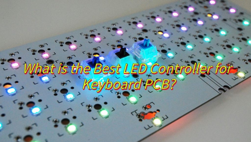
What Is the Best LED Controller for Keyboard PCB?
- Compatibility: Works with your keyboard’s hardware and software.
- Programmability: Supports multiple programming languages and libraries for complex effects.
- Processing Power: Enough power to smoothly control multiple LEDs.
- Power Efficiency: Efficient power usage to extend battery life.
- Community Support: Active community for help and resources.

How to Design a DIY Mechanical Keyboard LED PCB?
Here are steps for DIY mechanical keyboard LED PCB:
â1. Confirm Switch and LED Requirementsâ
- Switch Compatibilityâ: Select mechanical switch type (e.g., Cherry MX) and verify footprint dimensions. Design a switch matrix (rows/columns) with N-key rollover using 1N4148 diodes. Assign rows/columns to MCU GPIO pins (e.g., ATmega32U4).
- LED Systemâ: For single-color LEDs, calculate resistor values by subtracting the LED forward voltage from the power supply voltage and dividing by the desired current. For RGB LEDs (WS2812B), chain data lines (DINâDOUT) with 0.1”F decoupling capacitors per LED and a 220Ω resistor on the data line. Ensure total LED power consumption stays below 500mA for USB compliance.
â2. Power Circuit Design
- âVoltage Regulationâ: Integrate a 5V to 3.3V LDO (e.g., AP2112K-3.3V) for MCU power. Include a 10”F bulk capacitor at the USB input and 100nF decoupling capacitors near each IC.
- âProtectionâ: Add a 500mA PTC fuse on the VBUS line to prevent overcurrent damage.
â3. PCB Layer Stack-up and Routing
- â2-Layer Designâ: Route switch rows/columns on the top layer and dedicate the bottom layer to ground. For RGB-heavy designs, use a 4-layer stack with dedicated power/ground planes.
- âSignal Isolationâ: Route switch matrix traces perpendicular to RGB data lines to minimize interference. Keep RGB data traces under 30cm and use 0.2mm trace width with 0.1mm spacing for impedance control (~50â60Ω).
â4. Thermal Managementâ
- âAluminum-Core PCBâ: 1.6mm aluminum substrates (e.g., Bergquist MP-06503) for high-power LED setups. Place thermal vias (0.3mm drill, 0.6mm pad) under LEDs to transfer heat to the core.
- âMountingâ: Secure LEDs with thermal adhesive (e.g., Arctic Silver) for improved heat dissipation.
â5. Component Placement
- âSwitchesâ: Align to a 19.05mm grid (ANSI/ISO standard). Include hot-swap sockets if required.
- âLEDsâ: Position 2.5mm below switch stems for uniform backlighting. Avoid placing LEDs near mounting screws or plate cutouts.
- âMCU and USBâ: Place the MCU close to the USB connector. Add ESD protection (e.g., USBLC6-2SC6) on the USB data lines.
â6. Firmware Configurationâ
- âMatrix Mappingâ: Define row/column GPIO assignments in firmware. Assign the RGB data pin (e.g., RGB_DI_PIN = GP16).
- âLED Controlâ: Implement libraries like Fast LED for animations. Apply gamma correction to ensure color accuracy.
â7. Prototype Assembly and Testingâ
- âFabricationâ: Order prototypes with ENIG finish and impedance-controlled traces. Specify 0.5oz copper for cost efficiency.
- Functional Testsâ: Measure USB current draw at max brightness; ensure it stays below 500mA.
- Thermal Validationâ: Use a thermal camera to check LED temperatures (<60°C under sustained use).
How to Avoid Keyboard LED Polarity Issues?
- Align LED orientationâ with the PCBâs polarity symbols (e.g., anode/cathode markers like “+/-” labels or silkscreen arrows)â.
- Verify PCB polarity markingsâ using clear indicators (e.g., asymmetrical footprints or “+” labels) to prevent reversed installationâ.
- Test LEDs before solderingâ by placing them loosely on the PCB and powering the board to confirm functionalityâ.
- Ensure correct wiring alignmentâ for power (VCC), ground (GND), and data lines (DIN/DOUT) to match the LED pinoutâ.
- Use a multimeterâ to check continuity between LED pins and PCB pads for proper polarity alignmentâ.
- Select PCBs with reverse-protection featuresâ like polarity diodes or reverse-voltage-tolerant LEDs (e.g., WS2813)â.
- Follow manufacturer pinout guidesâ from datasheets to confirm LED and PCB specifications (e.g., WS2812B pin 1 = VCC)â.
- Inspect solder jointsâ to fix misaligned pins or accidental bridges that short-circuit connectionsâ.
- Label custom PCBsâ with polarity symbols or color-coded silkscreen layers (e.g., red for VCC, black for GND)â.
- Update firmware settingsâ (e.g., QMK) to align GPIO pin configurations with the PCBâs electrical polarityâ.

How to Achieve RGB LED Effects on Keyboard PCB?
Here are steps to how to achieve RGB LED effects on keyboard PCB:
â1. Hardware Designâ
- Use a PCB that supports RGB LEDs (such as aluminum substrates for heat dissipation), and the pad size is suitable for 5050 LEDs (5mmx5mm).
- Choose addressable RGB LEDs (such as WS2812B) or ordinary RGB LEDs with driver circuits (such as MOSFET+PWM).
- Integrate a microcontroller (such as STM32F103) to manage signals and protocols (IÂČC/SPI).
2. Welding and Assemblyâ
- The soldering iron temperature is <350°C to solder the LED to avoid damage.
- A series current limiting resistor (such as 0805 68Ω) prevents overcurrent.
â3. Firmware Programmingâ
- Use Arduino or QMK to program dynamic effects such as breathing and rainbow.
- Control brightness and RGB color mixing (0-255) through PWM dimming.
4. Software Configurationâ
- Use Open RGB to customize single-key lighting effects and synchronize system themes.
- Program macros or SDK to achieve dynamic responses (such as key-triggered lighting effects).
5. Test Optimizationâ
- Use a multimeter to check the circuit and AOI to detect the quality of solder joints.
- Optimize code to reduce delays and ensure smooth lighting effects.
How to Choose the Best Keyboard LED PCB Design Service?
- IP Protectionâ: Ensure providers enforce strict NDAs. Like EBest Circuit (Best Technology), we have encrypted storage and physically isolated R&D environments to safeguard firmware code and LED matrix control logic.
- Transparent Processâ: Prioritize modular designs (e.g., detachable LED driver layers) supported by real-time collaboration tools and standardized Gerber/BOM files for seamless production handoffs.
- High-Density Expertiseâ: Prioritize vendors with proven success in 8×16 RGB matrices, resolving ghosting/thermal issues, and delivering â„200Hz refresh rates with ±5% current accuracy.
- Signal & Thermal Performanceâ: Verify PWM interference analysis in keyboard LED matrix layouts and thermal solutions (aluminum substrates, optimized copper layers) to prevent overheating.
- Customization & Efficiencyâ: Demand QMK-compatible firmware for low-latency effects (<3ms) and high-reflectivity materials (â„85%) to minimize power consumption in backlit designs.

Why is My Keyboard LED PCB Not Working?
- Insufficient Powerâ: If USB power exceeds limits (e.g., 1A for 50 LEDs), use an external power supply or reduce the number of LEDs.
- Voltage Dropâ: Measure voltage at the LED endpoints. If below 4.5V (for 5V LEDs), thicken power traces or add external 5V power injection.â
- Broken Connections or Cold Solder Jointsâ: Ensure the data line (DIN) is sequentially soldered. Re-solder loose joints.
- Short Circuitsâ: Check for accidental solder bridges or debris between pins/traces.â
- Incorrect Pin Mappingâ: Verify the GPIO pin assigned to the data line in firmware (e.g., QMK) matches the PCB design.
- Missing Driversâ: Install libraries like Fast LED or update MCU firmware to support LED protocols (e.g., WS2812B).â
- Burned LEDs/MCUâ: Test components individually and replace faulty ones.
- Broken PCB Tracesâ: Check for broken traces in high-current areas (e.g., power lines) with a multimeter.
Can You Build a Keyboard LED Only PCB?
Yes, you can build a keyboard PCB solely for LEDs, but it requires designing a dedicated circuit for power delivery and control signals. Focus on high-current traces (â„1A) to handle multiple LEDs, integrate voltage regulation (3.3V/5V), and support addressable protocols (e.g., WS2812B) with proper data-line routing. Ensure physical spacing avoids interference between LEDs and omit switch footprints. Pair it with a compatible controller (e.g., RP2040) for firmware-driven effects. This setup suits decorative lighting or auxiliary backlighting but lacks switch functionality.


