
Would you want to get more information about LED polarity PCB? Let’s explore more about its function, application and identify LED polarity ways.
As a LED polarity PCB manufacturer, Best technology focus on LED polarity PCB solution over 18 years, including LED polarity PCB design and manufacturing. Our advanced etching and plating processes ensure crystal-clear polarity markings (e.g., 3-dot systems) to eliminate assembly errors and reverse-connection risks. Rigorous quality control includes AOI to verify polarity alignment during production and thermal stress testing to validate PCB durability under high-current LED drivers. We design asymmetric footprints with enlarged cathode pads and integrate silkscreen clues (arrows, “–” symbols) tailored to client specifications, adhering to IPC-7351 standards. With custom prototyping services and datasheet-backed technical support, we ensure polarity integrity from design to mass production, minimizing circuit damage risks. Partner with us for mission-critical LED PCBs that combine precision, compliance, and fail-safe performance. Contact us today for a competitive quote: sales@bestpcbs.com
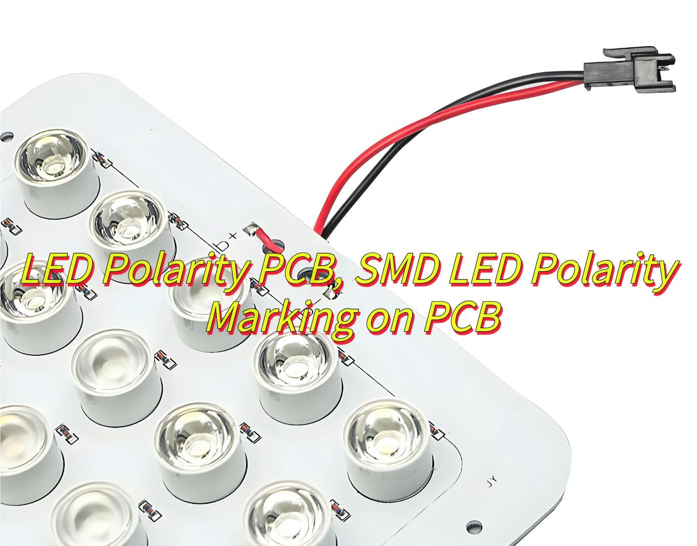
What Is LED Polarity PCB?
An LED Polarity PCB is a printed circuit board (PCB) specifically designed to accommodate Light Emitting Diodes (LEDs) while ensuring their correct electrical polarity. LEDs are diodes, meaning they allow current to flow in only one direction. Reversing the polarity can prevent the LED from lighting up or cause permanent damage.
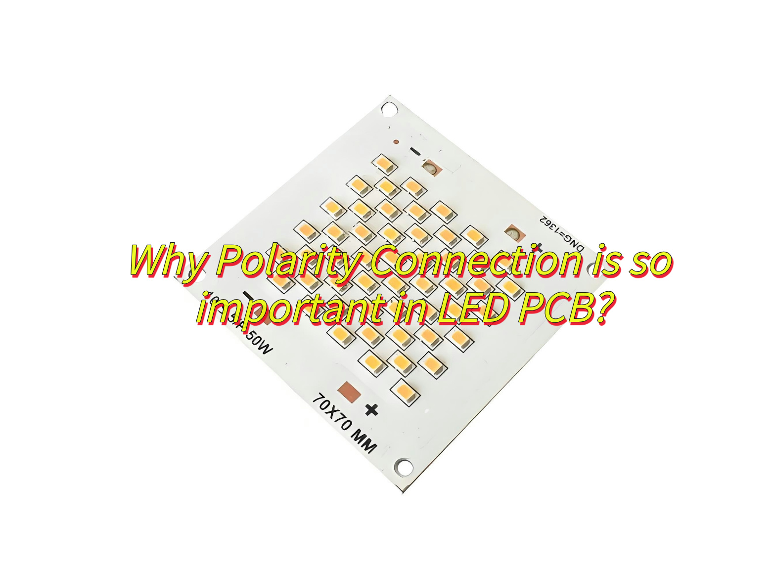
Why Polarity Connection is so important in LED PCB?
- Unidirectional Operation: LEDs function only with correct (+/-) alignment. Reverse polarity blocks current flow, preventing illumination.
- Component Protection: Incorrect polarity causes reverse bias, generating excessive heat that degrades or destroys LEDs.
- Circuit Integrity: Proper polarity ensures designed current paths, avoiding voltage drops, flickering, or cascading failures.
- Performance Stability: Correct alignment maintains brightness consistency, efficiency, and lifespan.
- Cost Avoidance: Eliminates rework, scrap, and warranty issues from polarity-related defects.
What Are Application of LED Polarity PCB?
Applications of LED Polarity PCB:
- Lighting Systems-Used in LED bulbs, streetlights, and industrial lighting for efficient heat dissipation and stable current flow.
- Automotive Lighting- Critical for headlights, taillights, and interior lighting to prevent reverse-bias damage and ensure reliability.
- Consumer Electronics-Enables backlighting in TVs, smartphones, and displays by aligning polarity to avoid flickering or uneven illumination.
- Signage and Advertising-Powers LED billboards, matrix displays, and decorative lighting with consistent color and brightness.
- Medical Devices-Used in surgical tools and diagnostic equipment for reliable, flicker-free illumination.
- Industrial Equipment-Supports machine vision systems and indicator lights with robust polarity-sensitive designs.

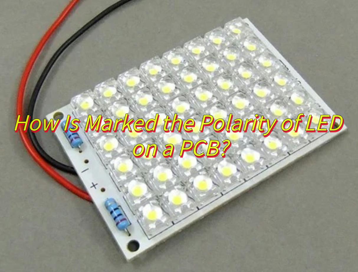
How Is Marked the Polarity of LED on a PCB?
Here are some ways to identify LED polarity on PCBs with markings and symbols:
Silkscreen Labels:
- “+” or “–”: Explicit symbols printed near pads.
- “A” (Anode) / “K” (Cathode): Text labels for clarity.
Pad Shape/Size:
- Square Pad: Often denotes anode (+).
- Round Pad: Typically marks cathode (–).
Polarity Symbols:
- Arrow or Line: Points toward the cathode (–) direction.
Component Outline:
- Flat Edge: Silkscreen outline matches LED’s flat side (cathode).
Color Coding:
- Red traces/pads for anode (+), black for cathode (–).
Test Points
- “+V” or “GND”: Voltage labels for debugging.
Documentation:
- Assembly Notes: Schematics or BOMs specify polarity alignment.
SMD LEDs
- Dot/Line: Package marking aligns with PCB’s cathode indicator.
How to Check SMD LED Polarity on PCBs Using 3-Dot Markings?
This is how to check SMD LED polarity on PCBs by 3-dot markings:
Locate the 3-Dot Pattern
- Identify three small dots or marks near the SMD LED footprint. These are often arranged in a triangular or linear pattern.
Analyze Dot Orientation
- Triangular arrangement: The dot closest to the PCB edge or silkscreen outline typically aligns with the cathode (–).
- Linear arrangement: The middle dot or offset dot often marks the cathode (–).
Cross-Check with Silkscreen Symbols
- Verify if the dots correlate with a flat-edge indicator, arrow, or ”–” symbol printed nearby.
Confirm via Pad Design
- If the cathode pad is round/oval or smaller, ensure the 3-dot marking aligns with this pad.
Review Documentation
- Check schematics or assembly notes for explicit explanations of 3-dot polarity conventions.
Can You Determine SMD LED Polarity on PCBs Without Markings or Symbols?
Yes, here are some methods about how to determine SMD LED polarity on PCBs without marking or symbols:
Check LED Package Features
- Look for a green dot or notched corner on the LED body, which typically marks the cathode (–).
- Some LEDs have a flat edge or inverted triangle; the flat side or triangle’s base aligns with the cathode (–).
Analyze PCB Pad Design
- The cathode (–) pad is often larger or rectangular, while the anode (+) pad is smaller or rounded.
- Follow adjacent traces: The cathode may connect to ground (GND) or a shared negative rail.
Use a Multimeter
- Set to diode test mode. The LED lights up when the red probe touches the anode (+) and the black probe connects to the cathode (–).
Cross-Reference Silkscreen Clues
- Check for subtle arrows, “–” symbols, or “匚” outlines near the LED footprint, which often indicate the cathode.
Verify with Datasheets
- Consult the component datasheet for explicit polarity diagrams if available.
Why Reversing SMD LED Polarity on PCBs Can Damage Your Circuit?
Here are reasons why reversing SMD LED polarity on PCBs can damages circuits:
- Exceeding Reverse Voltage Limits-LEDs have low reverse breakdown voltage (typically 5–10V). Reverse connection applies full supply voltage (e.g., 12V, 24V) across the LED, exceeding this limit and causing instant failure.
- Current Surge Risks-In reverse bias, LEDs act as open circuits until breakdown occurs. Post-breakdown, sudden current flow bypasses current-limiting resistors, damaging the LED and overloading drivers/ICs.
- Impact on Driver Circuits-Constant-current LED drivers (e.g., in backlighting) malfunction when polarity is reversed, potentially shorting outputs or overheating due to unregulated current.
- Trace/Component Stress-Reverse polarity forces current to flow through unintended paths, stressing PCB traces or nearby components (e.g., capacitors, resistors).
- Collateral Damage-Failed LEDs can short internally, creating direct connections between power and ground rails, risking system-wide failures.
FAQs of LED Polarity PCB
Q1:What types of LEDs are commonly used in PCBs?
A1:Common types of LEDs used in PCBs include through-hole LEDs, surface-mount LEDs (SMD), and chip-on-board (COB) LEDs. Each has its own polarity identification, but the basic concept remains the same.
Q2:Is it important to check LED polarity when assembling the PCB?
A2:Yes, checking the LED polarity is crucial to ensure the LEDs function as expected. Many PCB assembly services provide clear instructions or visual indicators to guide the correct placement of polarized components like LEDs.
Q3:What tools can help check LED polarity on a PCB?
A3:A multimeter can be used to check the polarity of LEDs, by testing the forward voltage drop when applying a small current. Additionally, a polarized component tester or a microscope can help visually confirm the polarity during assembly.
Q4:How does the polarity of an LED affect the overall performance of the circuit?
A4:Correct LED polarity ensures that the LED operates at its optimal brightness and efficiency. Incorrect polarity can lead to malfunctioning or failure of the LED, which can disrupt the entire circuit, especially in critical applications.
Q5:Can a reverse-polarized LED be repaired?
A5:Typically, an LED cannot be repaired if it is installed with reversed polarity, as it can be permanently damaged. It is best to replace the LED if polarity is reversed.
You may also like


Tags: LED Polarity PCB