
When it comes to reliable and advanced PCB solutions, Best Technology leads the way. With more than 18 years in the industry, we provide custom circuit board manufacturing for global clients. From prototype to volume production, we help you build better products with very good heat dissipation and military-grade quality. Our strength lies in metal-based PCBs, especially pcb aluminium substrates. These are widely used in LED, automotive, telecom, and power industries. With precision equipment and a strict quality system, we ensure high-performance boards that meet your needs.
What Is a PCB Aluminium Substrate?
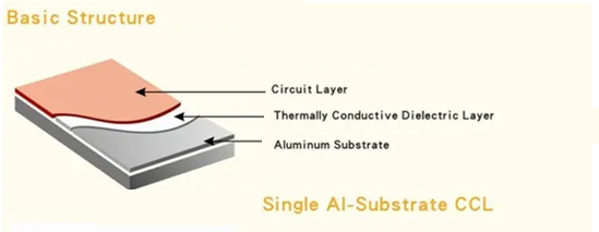
A PCB aluminium substrate is a type of metal-based printed circuit board. (MCPCB) It uses aluminum as its base material instead of traditional FR4. This base supports layers of dielectric, and copper circuits. Aluminum PCBs offer strong heat dissipation and structural support compared with normal rigid PCB. The aluminum base acts as a heat sink. This makes the substrate ideal for high-power or thermally sensitive applications. In simple terms, it’s a PCB built on aluminum rather than fiberglass.
Performance of Aluminium Substrate PCB in LED
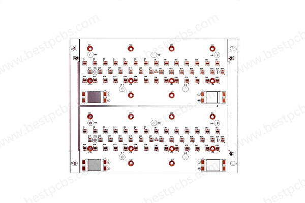
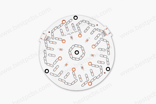
Aluminum substrate PCBs are the backbone of today’s LED lighting systems. Their ability to manage heat is the most critical factor. When LEDs operate, they generate a lot of heat at the junction point. If that heat isn’t removed quickly, the LED’s brightness fades, and its lifespan shortens. Using an aluminum board for LED, we can get these benefits:
- Efficient heat dissipation: The aluminum metal base acts as a built-in heat sink, pulling heat away from the LED source and spreading it across the board.
- Improved reliability: By reducing thermal stress, the board helps extend the lifespan of each LED component. That means longer-lasting light and less need for replacement.
- Stable light output: Overheating causes LEDs to dim. Aluminum PCBs maintain the thermal balance so that brightness stays consistent. Whether it’s a street lamp or a small indoor fixture, aluminum PCBs deliver stable operation.
- Compact design: Since aluminum boards manage heat on their own, there’s no need for bulky external cooling systems.
- Cost-effective: Although slightly more expensive than FR4, their longer lifespan and lower maintenance needs make them a better investment for lighting manufacturers.
6061 vs. 5052 vs. 1060 Aluminum Substrate
In the aluminum PCB manufacturing, the common aluminium substrates that manufacturers always use are 6061 aluminum substrate, 5052 aluminum substrate and 1060 substrate. All of them are aluminum allay, but the compositions and purity are different, so that the performance different too.
5052 aluminum sheet belongs to Al-Mg alloy, the main alloying element is magnesium, which has a content of 2.2% ~ 2.8%. In addition, it also contains a small amount of chromium (0.15%-0.35%) and other elements. The addition of which is intended to improve the strength and corrosion resistance of the alloy. 6061 aluminum sheet is Al-Mg-Si alloy, in addition to magnesium (0.8%-1.2%) and silicon (0.4%-0.8%) as the main alloying elements, copper (0.15%-0.4%) and zinc (less than 0.25%) are also added. 1060 aluminum material belongs to pure aluminum sheet, with an aluminum content of more than 99.6%, and almost no other alloying elements. Different alloy components form the basis of the different performances of these aluminum substrates. Below is a table comparison show the differences between each of them:
| Property | 6061 Aluminum | 5052 Aluminum | 1060 Aluminum |
| Composition | Magnesium & silicon alloy | Magnesium alloy | Pure aluminum (≥99.6%) |
| Thermal Conductivity | Moderate (150 W/m·K) | High (160 W/m·K) | Very high (≈237 W/m·K) |
| Strength of Extension | 290MPa | 215MPa | Low |
| Hardness | 95HB | 65HB | 30HB |
| Elongation | 10-18% | 12-25% | 5% |
| Formability | Low | High | High |
| Corrosion Resistance | Good | Excellent | Good |
| Common Uses | Structural parts, high-load PCBs | LED lights, flexible designs | High heat-dissipation PCBs |
| Cost | Higher | Medium | Lower |
So how to choose the suitable substrate for your aluminum PCB board? Follow this rule:
- Choose 1060 if your project needs maximum thermal conductivity.
- Choose 5052 if flexibility and corrosion resistance are more important.
- Choose 6061 if you need strength and rigidity for heavy-duty PCBs.
What Is the Dielectric Layer of Aluminum PCB?
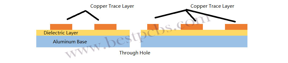
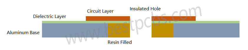
Aluminum substrate is generally composed of three layers: circuit layer (copper foil), dielectric layer and metal base. The dielectric layer is located between the circuit layer and the metal base layer, which acts as insulation and heat conduction. It is a polymer filled with high thermal conductivity and high insulation ceramic powder, make it is an ideal material with non-conductive but heat-conductive.
This dielectric layer has good heat conduction properties (thermal conductivity up to 3.0W/m-K), it is the key to thermal performance. It allows heat to pass from the copper to the aluminum while keeping them electrically isolated. The dielectric must have low thermal resistance and high breakdown voltage. Materials used often include ceramic-filled epoxy or polyimide. These support thermal conductivity while maintaining safety.
What Is the Difference Between FR4 and Aluminum PCB?
FR4 PCBs use fiberglass as a base. They are cheaper and more common. But they are poor at dissipating heat. They also deform more under thermal stress. Aluminum PCBs, on the other hand, handle heat much better. The aluminum pcb thermal conductivity is usually between 1.0 to 3.0 W/m·K. In contrast, FR4 is less than 0.3 W/m·K. That means aluminum PCBs can move heat away much faster. Here we listing the main differences between two of them:
| Feature | FR4 PCB | Aluminum PCB |
| Base Material | Fiberglass-reinforced epoxy | Aluminum metal |
| Thermal Conductivity | ≈0.3 W/m·K | 1–3 W/m·K |
| Heat Dissipation | Poor | Excellent |
| Mechanical Strength | Moderate | High |
| EMI Shielding | Weak | Strong |
| Cost (under the same design complexity situation) | Lower | Slightly higher |
| Use Cases | Consumer electronics, PCs | Mainly used in led lights, automotive, power modules |
| Thickness Options | 0.10mm, 0.12mm, 0.15mm, 0.20mm, 0.25mm, 0.30mm, 0.40mm, 0.50mm, 0.60mm, 0.80mm, 1.0 mm, 1.2 mm, 1.6mm, >=2.0 mm | 0.30mm, 0.40mm, 0.50mm, 0.60mm, 0.80mm, 1.0 mm, 1.2 mm, 1.6mm, 2.0 mm, 2.4mm, 3.0mm (exclude copper) |
| Weight | Much lighter | Heavier but lighter than copper pcb |
| Environment Tolerance | Lower heat resistance | Withstands high temperatures |
How Do You Make Aluminium PCB?
The manufacturing process of aluminum PCB is almost the same as normal FR4 PCB, except the lamination process of dielectric layer, aluminum and copper. This also is the biggest manufacturing difficult that faced by manufacturers, especially for multi-layer aluminum PCB. For the single & double sided aluminum PCB, the aluminum substrate we purchased from the manufacturers are laminated with dielectric, so we do not need to laminate again. In addition to this, the manufacturing process of aluminum PCB with insulated hole and without insulated hole are different.
- Single-sided Aluminum PCB without insulated hole:
Cutting raw material (substrate laminated with dielectric layer) — Circuit layer generation (D-E-S) — Solder Mask – Silkscreen — Surface Treatment — Stripping — Drill Holes — Outline (V-cut – Routing – Die Punching) — QC — Package & Delivery
- Single-sided Aluminum PCB with insulated hole:
Cutting raw material (substrate without laminated with dielectric layer) — Drill larger holes — Filled resin with holes — Lamination (dielectric layer + copper + aluminum base) — Circuit layer generation (D-E-S) — Solder Mask – Silkscreen — Surface Treatment — Stripping — Drill Holes — Outline (V-cut – Routing – Die Punching) — QC — Package & Delivery
Manufacturing Difficulties of Aluminum PCBs
Working with aluminum is not the same as working with FR4. It brings challenges, especially for a professional aluminum PCB manufacturer.
1. Mechanical Processing
Drilling holes on aluminum PCBs is possible, but the inner walls and board edges must be completely free of burrs. Even a slight burr can cause the board to fail the high-voltage test. Milling the outline is also quite difficult. The milling cutter used for FR4 PCB board has a relatively low hardness, while the milling cutter used for aluminum substrate has a high hardness. During the processing, the milling cutter for fiberglass board production has a high speed, while the milling cutter for aluminum substrate production has a speed at least 2/3 slower. As an alternative, punching with high-precision dies is often used—but die making requires exceptional skill, making this one of the main challenges in aluminum PCB manufacturing.
After punching, the edges must be clean and smooth, without any burrs or damage to the solder mask along the edges. Most factories use compound dies. Holes are punched from the circuit side, and the outline is punched from the aluminum side. This requires specific techniques, such as upward shearing and downward pulling during punching. Even after punching, the board’s warpage must be strictly controlled and should remain under 0.5%.
2. Protecting the Aluminum Surface During Processing
The aluminum base must remain completely free of scratches throughout the entire production process. Any direct contact with hands or chemicals can cause surface discoloration or oxidation, which are absolutely unacceptable. In many cases, re-polishing the aluminum surface is not allowed by customers. So, avoiding even the slightest damage to the aluminum layer is another major difficulty in the production process.
Some manufacturers use surface passivation treatments, while others apply protective films before and after hot air solder leveling (HASL). There are countless tricks and methods used to keep the surface clean—every factory has its own unique way of doing it.
3. High-Voltage Testing Requirements
For telecom power supply boards, 100% high-voltage testing is often mandatory. Some clients require DC testing, while others specify AC, typically at 1500V or 1600V for durations of 5 to 10 seconds. Every single board must pass this test.
Even the smallest contamination on the surface, burrs on holes or edges, jagged traces, or damage to the insulation layer can lead to arcing, leakage, or dielectric breakdown during testing. Boards that show signs of delamination or bubbling during the test are automatically rejected.
Despite these, trusted manufacturers like Best Technology handle it well. Our experience helps solve such problems early in the process.
How Much Does Aluminum PCB Cost?
Many factors influence the pcb aluminium substrate price. These include:
- Aluminum grade (6061, 5052, or 1060)
- Thickness of copper and base layer
- Board size and layer count
- Surface finish type
- Quantity ordered
- Special design features (e.g., thermal vias, contours)
In general, aluminum PCBs cost more than FR4 boards. But for heat-sensitive designs, the added cost pays off in reliability.
For instance, a basic one-layer aluminum PCB may start from $1.0–$5.0 per unit in bulk. Complex designs with multi-layers or special finishes can go higher. Best Technology offer competitive pricing without cutting corners. We also provide quick prototypes aluminium PCB substrate and full-scale production to meet your timeline and budget.
If you are interested in PCB aluminium substrate or aluminum PCB manufacturing, contact us today to learn more about our aluminum PCB board solutions. Let’s build something great together—strong, reliable, and ready for tomorrow’s tech.
You may also like


Tags: aluminum board for led, aluminum pcb manufacturer, aluminum pcb thermal conductivity, aluminum pcb vs fr4, pcb aluminium substrate, pcb aluminium substrate price