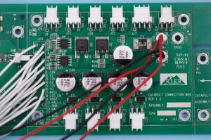
Nowadays, printed circuit board plays a more and more important role in electronic products, whether for personal use or commercial use, failure PCB can effect the usage of electronic products and cause a serious consequence. So, how to quickly detect the PCB fault problem?
Here, Best Tech summarized seven methods to locate fault PCB quickly.
- Use testing equipment
The typical equipment including Automated Optical Inspection (AOI) equipment, X-Ray Fluoroscopy, Optical Microscopy, 1000x magnifying glass. When some failures happen and we donât know what is the specific position, properly use of these detection devices can help us quickly locate the faulty PCB.
- Visual inspection
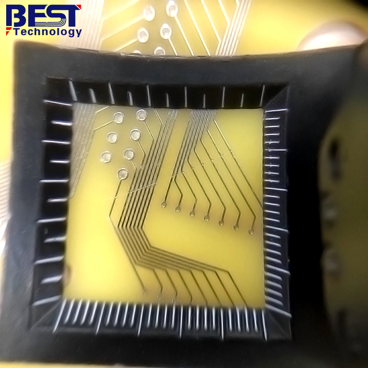
Visual inspection is the most common and easy method to position those defectives in printed circuit board. It can identify defects such as overlapped marks, solder joint short, signs of overheating circuit boards, and burned components. When some problems are difficult to identify with our naked eye, magnifying glasses can help to identify some short circuits, welding bridges, open circuits, solder joints and circuit board wiring cracks, component offset, etc.
- Components inspection
If the printed circuit board was assembled with some electronic components, we can perform a components inspection to locate the failure. Especially when low resistance is detected between the component pins, it is best to remove the component from the PCB circuit for specialized testing. If the resistance is still low, then this component is the culprit, otherwise further investigation will be required.
- Power on printed circuit board
Visual inspection is only suitable for checking the appearance of outer layers of the circuit board, instead of for checking the inner layer of the circuit board. If there are no visible defects in the appearance, you can power up/on the board and perform a more detailed test to determine whether the board is working properly or not.
- Low voltage measurement
The first thing to confirm is whether the voltage of each chip power pin is normal, and then check whether the various reference voltages are normal, and whether the working voltage of each point is normal. Since the copper trace on the circuit board has resistance, the voltage generated through different parts of the copper trace is also different. Then you can use a voltmeter or multimeter to measure the voltage between different parts along a short. If you find that the voltage value is getting smaller and smaller, you are getting closer to find out a short circuit.
For a simple example, when a typical silicon triode is on, the BE junction voltage is around 0.7V, while the CE junction voltage is around 0.3V or less. If the BE junction voltage of a triode is greater than 0.7V (except for special triode, such as the Darlington tube), the BE junction may be open.
- Touch circuit board with your finger
In general, when some failure happened, some areas on the circuit board will be getting more and more heat. In this time, we can try to touch the circuit board with fingers to find out areas with heat, and it will help us to pinpoint the problem. However, be careful to use short-circuit copper trace power supply and avoid burns or electric shock.
- Repair short/open
After identifying a short or open circuit on the PCB, the next step is to isolate the problem. While this is easy to do on the outer surface of the board, it is a challenge for the inner layers. Possible solutions include drilling through holes or cutting appropriate external copper traces.
This is the end of this article, if you have more better methods to locate the failure printed circuit board, warm welcome to contact us, we can analyze together.


