

Metal core printed circiut boards are used where a large of heat are generated in the circuit, and the heat needs to be dissipated quickly to avoid overheat. These boards offer good thermal conductivity and dimensional stability. The aluminum core can reduce the overall weight of your board.
What is Metal Core Printed Circuit Board?
A metal core printed circuit board (MCPCB) is a type of PCB that incorporates a metal core, usually aluminum or copper, as its base material. This core helps to enhance the board’s thermal management capabilities. Unlike traditional PCBs made of fiberglass (FR4), MCPCBs are designed to dissipate heat more effectively, making them ideal for applications where heat dissipation is crucial.
MCPCBs are also referred to as insulated metallic substrate (IMS), or insulated metal PCBs (IMPCB), thermal-clad PCBs. A typical metal core PCB is made of thermal insulating layer (dielectric layer), metal base and copper foil.
The basic constructure of a metal core circuit board includes:
- Silkscreen
- Solder mask (S/M)
- Circuit layer (copper foil layer)
- Dielectric layer
- Metal core base
What are Metal Core PCBs Used For?
Metal core PCBs are popular because of its good thermal management. It utilizes in various applications that demand efficient heat dissipation and high thermal performance. Here are some common applications that metal core printed circuit board will be used in.
- LED lighting
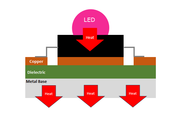
MCPCBs are widely used in LED lighting systems due to their excellent thermal management properties. LEDs generate a significant amount of heat, and metal core PCBs help to dissipate this heat effectively, ensuring longer lifespan and consistent performance of the LEDs.
- Power supplies
High-power supply units benefit from MCPCBs as they can handle the heat generated by power components. This helps in maintaining the stability and efficiency of the power supply over time.
- Automotive electronics
In the automotive industry, MCPCBs are used in various electronic control units (ECUs), lighting systems, and other high-power applications. The robust nature of MCPCBs makes them suitable for the harsh conditions experienced in automotive environments.
- Industrial equipment
Industrial machinery and equipment that operate under high temperatures or require high power output use MCPCBs for their thermal management capabilities. This ensures the reliability and longevity of the equipment.
- Telecommunications
Telecommunications equipment, such as base stations and routers, use MCPCBs to manage the heat generated by high-speed and high-frequency operations, ensuring uninterrupted performance and reliability.
- Consumer electronics
High-performance consumer electronics, including laptops, smartphones, and gaming consoles. They install with MCPCBs to manage heat and improve device performance and lifespan.
What are the Advantages of Metal Core PCB?
Metal core PCBs are preferred for several reasons, primarily revolving around their superior heat dissipation capabilities and mechanical strength. Here are some main advantages of metal core PCBs.
- Superior thermal management
- Mechanical strength
- Compact design
- Enhanced performance
- Improved reliability
- Higher recyclability
- Cost Efficiency
- Dimension stability
- Size reduction
- Longer lifetime
What Metal is Used in PCBs?
The choice of metal in PCBs significantly affects their thermal and mechanical properties. The most commonly used metals in MCPCBs are aluminum and copper. Here’s a closer look at these materials:
Aluminum
- Thermal Conductivity: Aluminum has a thermal conductivity of approximately 1.0 to 2.0 W/mK, making it an excellent material for heat dissipation.
- Cost-Effective: Aluminum is relatively inexpensive compared to other metals, making it a cost-effective choice for many applications.
- Lightweight: Aluminum is lighter than copper, which can be beneficial in applications where weight is a concern.
- Corrosion Resistance: Aluminum naturally forms a protective oxide layer, enhancing its resistance to corrosion.
Copper
- Thermal Conductivity: Copper has a higher thermal conductivity than aluminum, ranging from 3.0 to 5.0 W/mK, providing superior heat dissipation.
- Electrical Conductivity: Copper is also an excellent conductor of electricity, which can improve the electrical performance of the PCB.
- Durability: Copper is more durable and resistant to wear and tear compared to aluminum, making it suitable for more demanding applications.
- Higher Cost: Copper is more expensive than aluminum, which can increase the cost of the PCB but is justified in applications requiring superior performance.
Other Metals
In some specialized applications, other metals like stainless steel or alloys might be used, but these are less common due to their specific properties and higher costs.
What is the difference between FR4 PCB and Aluminum PCB?
Aluminum PCB is a material based on aluminum base material, coated with an insulating layer and other conductive layers on the aluminum base material. FR4 is a glass fiber reinforced laminate, made of multi-layer fiber cloth and resin composite. In the following, we will introduce the difference between aluminum substrate and FR4 in terms of thermal conductivity, mechanical strength, manufacturing difficulty, application range and thermal expansion coefficient.
1. Aluminum substrate has good heat dissipation, and its thermal conductivity is about 10 times that of FR4.
2. The mechanical strength and toughness of the aluminum substrate are better than FR4, which is suitable for installing large components and making large-area pcb boards.
3. The production of aluminum substrate requires more process steps, and its production process is more complex than FR4, and the production cost is higher than FR4.
4. The aluminum substrate is suitable for high-power electronic products such as LED lighting, power supplies, inverters and solar inverters, and FR4 is suitable for low-power electronic products such as televisions, telephones and electronic game consoles.
5. The thermal expansion coefficient of aluminum substrate is close to that of copper foil, which is smaller than that of FR4, which is good for ensuring the quality and reliability of the circuit board.
How to Design Metal Core PCB?
Designing a metal core PCB is a complex process that includes several crucial steps. During the design, we should ensure the board meets the thermal, electrical, and mechanical requirements of the application. Below is a detailed guide to the MCPCB design process.
1. Define the Application Requirements
Before starting the design process, it’s essential to clearly define the requirements of your application. This includes understanding the thermal, electrical, and mechanical needs of the project. Determine the maximum operating temperature and the amount of heat that needs to be dissipated, ensuring the MCPCB can handle the thermal load effectively. Specify the electrical characteristics such as current load, voltage levels, and signal integrity requirements to ensure the board can deliver the necessary performance.
2. Select the Core Material
As mentioned above, there are two common metal materials used in this industry: aluminum alloy and copper core. They have unique characteristics and properties when used in device. So. choosing the appropriate metal core material is crucial for the performance of your electronic device. This table provides a side-by-side comparison of aluminum alloy and copper core materials, helping to choose the appropriate material when designing MCPCBs.
| Property | Aluminum | Copper |
| Thermal Conductivity | 1.0 – 2.0 W/mK | 3.0 – 5.0 W/mK |
| Electrical Conductivity | Lower than Copper | High |
| Weight | Light | Heavy |
| Cost | Lower | High |
| Mechanical Strength | Good | Excellent |
| Corrosion Resistance | Natural Protective Oxide Layer | Requires Additional Protection |
| Thermal Expansion Coefficient | Higher | Lower |
| Machinability | Good | More Difficult |
| Environmental Impact | Recyclable | Recyclable |
| Application Areas | LED Lighting, Consumer Electronics, High-Performance | Electronics, Industrial Equipment |
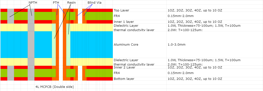
3. Determine the Layer Stack-Up
The layer stack-up defines the arrangement of the different layers in the PCB. A typical MCPCB stack-up includes:
- Top Copper Layer: The conductive layer where components are mounted.
- Dielectric Layer: An insulating layer that separates the copper layer from the metal core. It has good thermal conductivity to transfer heat from the components to the metal core.
- Metal Core: The central layer made of aluminum or copper, which acts as a heat spreader.
- Bottom Copper Layer (optional): Used in double-sided MCPCBs for additional routing of traces.
4. Design the Circuit Layout
The circuit layout includes placing components and routing traces on the PCB. Key considerations include strategically placing heat-generating components to ensure efficient heat dissipation and keeping sensitive components away from high-heat areas. Trace routing should minimize electrical interference and maintain signal integrity, using wider traces for high-current paths to reduce resistance and heat generation. Implementing thermal vias enhances heat transfer from the top copper layer to the metal core by using plated through holes that connect the copper layer to the metal core, facilitating better heat dissipation.
5. Design for Manufacturability (DFM)
Ensuring that your design can be efficiently manufactured is critical. Maintain adequate clearances between traces, pads, and other features to meet MCPCB manufacturing capabilities and avoid short circuits. Use standard drill sizes to reduce manufacturing complexity and cost. Apply a solder mask to prevent solder bridges and protect the copper traces from oxidation. Use clear and legible silkscreen markings for component identification and assembly instructions. You can communicate with your supplier and ask for a capability chart, so that can save much time on design phase.
6. Prototype and Test
Once the design is validated, create a prototype of the MCPCB and conduct thorough testing. Measure the actual thermal performance under operational conditions to verify the simulation results. Test the functionality of the PCB in the intended application environment to ensure it meets all performance requirements. Conduct reliability tests such as thermal cycling, vibration testing, and humidity testing to assess the durability of the MCPCB.
EBest Circuit (Best Technology) – A Leading MCPCB Manufacturer in Asia
With 18+ years of experience in the PCB industry, EBest Circuit (Best Technology) has a deep understanding of the complexities involved in MCPCB production. Our team of experts is adept at designing and manufacturing MCPCBs that deliver optimal performance. EBest Circuit (Best Technology) offers customized turn-key solutions tailored to the specific needs of our clients. Whether it’s a unique design requirement or a specific material preference, we provide flexible options to meet diverse demands.
Contact EBest Circuit (Best Technology), get your quote right now to make your own metal core circuit boards!