LED lights have become an integral part of modern lighting solutions, featuring energy-saving, durability, and versatility. But a common question is, do you think LED lights need a circuit board to work?
What is a LED circuit board?
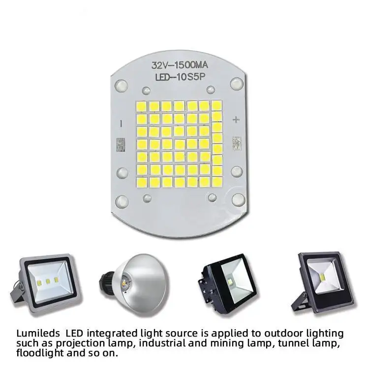
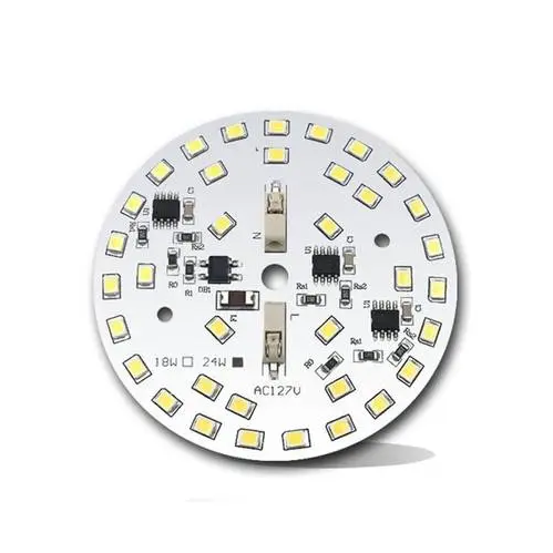
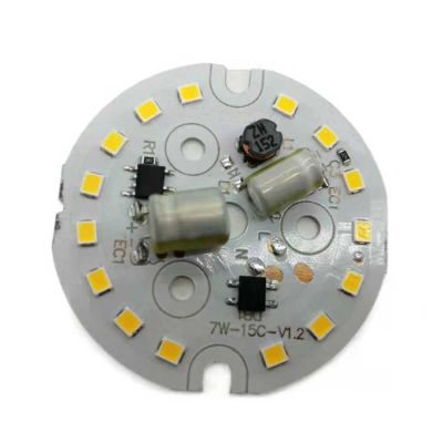
An LED circuit board is a platform used to power and control light-emitting diodes (LEDs). Essentially, it is the basis for connecting all the necessary electronic components (such as resistors, capacitors, and diodes) to ensure that the LED operates safely and efficiently.
Circuit boards used for LEDs are usually metal core printed circuit boards (MCPCBs) because they have excellent heat dissipation properties. This is important because although LEDs are highly efficient, they still generate heat. Without proper heat management, this can lead to poor performance or shortened life of the LED.
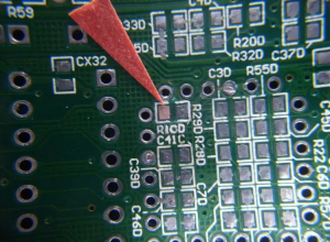
The design and manufacture of LED circuit boards involves many aspects, including the layout of the board, the soldering of components, and the design of the driver circuit. The driver circuit is the core part of the LED circuit board, which is responsible for converting the input AC power into DC power suitable for LED use, while providing stable current and voltage to ensure the normal operation and long life of the LED.
LED circuit boards are used in a wide range of applications, from small consumer electronics to industrial lighting and automotive headlights. They provide a simplified way to control and adjust LEDs while ensuring effective heat management.
How to make a LED light circuit board?
The process of making an LED light circuit board involves multiple steps, including soldering, self-testing, cleaning, grinding, and wiring.
1. Soldering:
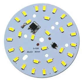
Determine the direction of the light, the side with the black rectangle is the negative end. Determine the direction of the circuit board, the end with the inner and outer wiring ports is the upper left corner. Start from the upper left light and solder in sequence to ensure that each solder joint is full and clean, without cold solder joints or leaks.
2. Self-test:
After completing the soldering, check whether the solder joints have cold solder joints, leaks, etc. Use a multimeter to touch the positive and negative terminals of the circuit board to check whether the LED lights are on at the same time.
3. Cleaning:
Use 95% alcohol to scrub the circuit board to remove residues.
4. Rubbing:
Remove the LED light circuit board from the entire board, use fine sandpaper to grind off the burrs on the edges, and make the circuit board flat.
5. Wiring:
Use blue and black thin wires to connect the circuit board. The wiring point close to the inner circle is negative and connected to the black wire; the wiring point close to the outer circle is positive and connected to the red wire. Make sure the wire is connected from the back to the front.
6. Final self-check:
Check the wiring to ensure that each wire passes through the pad and the length of the wires on both sides of the pad left on the surface is as short as possible to ensure that the circuit board can work properly.
Each step is crucial, especially the welding and wiring parts, which need to be carefully operated to ensure the performance and safety of the circuit board.
How should an LED be connected in a circuit?
LEDs should be connected to the circuit through the correct wiring method to ensure their normal operation and extend their life.
First of all, there are three main wiring methods for LEDs: two-end wiring, single-end wiring and staggered wiring.
Two-end wiring is a commonly used wiring method in the early days. It is characterized by convenient wiring and simple operation. It is suitable for the replacement of fluorescent tubes.
Single-ended wiring is a safer wiring method, in which one end of the LED tube is not wired, and the two pins on the other end are respectively wired to the constant current drive power supply. This wiring method ensures that if one end of the LED tube is connected to AC power, the other end will never be charged.
Staggered wiring is an innovative wiring method that is compatible with a variety of electronic ballasts and can work normally without a starter.
When connecting LEDs, you need to pay attention to the following points:
Correctly distinguish the positive and negative poles of the LED, which can usually be judged by observing the appearance, using a multimeter or battery. Connect the anode of the LED to the positive pole of the power supply and the cathode to the negative pole of the power supply to ensure that the LED works properly.
Use appropriate resistors to limit the current to protect the LED from damage by overcurrent. The resistance value should be calculated based on the power supply voltage, the rated voltage of the LED, and the required current.
Keep the LED dry, avoid moisture or static interference, and pay attention to the temperature to avoid excessively high temperatures that affect its life and performance.
For the power connection of LED light strings, two basic forms can be used: positive connection and negative connection. The positive and negative poles of each light string correspond to the positive and negative poles of the power supply. When a large number of LED lights are connected in series, it is more practical to adopt a series-parallel combination strategy, and the number of parallel groups is determined by calculating the rated current of the power supply.
Do LED lights need special wiring?
LED lights do not require special wiring, but it is necessary to determine whether a grounding wire is required based on the specific situation of the lamp.
LED lights are usually designed without special wiring because they can be directly connected to AC power, thanks to the built-in rectifier of LED lights.
When installing LED lights, it is important to understand the difference between the live wire and the neutral wire, because although LED lights themselves work under DC power, they usually have built-in rectifiers and can be directly connected to household AC power.
When replacing traditional fluorescent tubes, it is necessary to remove the original ballast and starter, and directly connect the live wire and the neutral wire to both ends of the LED tube.
Regarding the issue of grounding wires, most LED lights on the market are double-insulated designs, which means that their housing and structure have met safety requirements, so no grounding wire is required. However, for lamps with metal shells, grounding is necessary to prevent people from getting electric shock when touching the bare metal.
In addition, if the bulb has a grounding wire, it is better to connect it, which can better ensure safety. It should be noted that Class III lamps are not allowed to be grounded because they use safety extra low voltage (SELV) and should be isolated from high voltage using an isolation transformer, and should not be grounded.
In summary, although LED lamps do not require special wiring, you should pay attention to safe wiring methods during installation, and judge whether a grounding wire is required according to the specific situation of the lamp to ensure safety and prevent the risk of electric shock.
Where to put resistor in LED circuit board?
In the LED circuit, the resistor should be placed between the positive pole of the LED and the first LED, that is, in front of each string of lamp beads. This placement does not depend on the specific location of the resistor, because the resistor and the LED are in series, which means that whether the resistor is placed in front of, behind, in the middle of each string of lamp beads, or anywhere randomly, the effect is the same.
This is because the main function of the resistor is to control the current through the LED by consuming a certain voltage and current, ensuring that the LED operates at a normal operating current and avoiding damage to the LED due to excessive current.
It is worth noting that although the position of the resistor has little effect on the LED, in actual circuit design, considering the simplicity and safety of the circuit, the resistor is usually placed close to the positive pole of the power supply. This design can avoid too many connection points in the circuit, thereby simplifying the circuit structure.
Conclusion:
LED lights usually require circuit boards for optimal performance, especially in complex or high-power applications. LED circuit boards ensure proper heat dissipation and current regulation, which are key factors in ensuring the service life and efficiency of the lighting system. BEST Technology has accumulated rich manufacturing experience in the design of LED circuit boards, and various different LED light circuits can be designed to the top level.