What is High Density Interconnect PCB?
High density Interconnect (HDI) PCB is a printed circuit board designed to meet the growing needs of modern electronic products. It allows for higher component density due to the use of thinner lines, smaller through-holes, and precise component placement. These boards are particularly popular in industries where miniaturization is key, such as smartphones, medical devices, and military equipment.

The HDI board uses the micro-blind hole technology to realize the circuit board design with high line distribution density, which is especially suitable for applications requiring high performance and high reliability. Compared with traditional PCBs, HDI boards have significant advantages in terms of volume, weight, wiring density and electrical performance, which can meet the electrical requirements of high-speed signals, provide impedance control of alternating current characteristics, high-frequency transmission capacity and reduce unnecessary radiation (EMI).
HDI PCBs use a combination of advanced technologies such as laser drilling and sequential lamination to enable denser wiring without compromising performance. By integrating smaller, more efficient through-holes, HDI boards offer greater functionality on a smaller footprint than traditional PCBs.
What is the Difference Between Connect and Interconnect?
The terms “connect” and “interconnect” may seem similar but serve distinct functions in electronics. “Connect” typically refers to the linking of two points, components, or circuits. This could be as simple as joining a wire to a terminal.
On the other hand, “interconnect” deals with more complex connections, usually involving the linking of multiple circuits or components within a system. In the context of HDI PCBs, interconnectivity is crucial because it defines how different layers and components of the board communicate. HDI technology optimizes these interconnections to make the board more efficient in terms of space and performance.
What is HDI PCB Stackup?
The stackup in HDI PCBs refers to how the multiple layers of the board are arranged. Stackups are critical in determining the board’s performance, particularly when it comes to signal integrity, power delivery, and heat dissipation. HDI stackups often involve intricate configurations that vary depending on the design’s complexity and purpose. Here are the most common types:
HDI PCB (1+N+1)
This is one of the simplest forms of HDI stackups, where “1+N+1” means there are two layers of high-density interconnect (one on each side) sandwiching N layers of traditional PCB. This structure is often used in applications where moderate complexity is required, providing a balance between performance and cost.

HDI PCB (2+N+2)
In this configuration, there are two HDI layers on each side of the N traditional layers. This setup allows for greater flexibility in routing, especially for complex designs requiring more components. The additional HDI layers enhance the boardās ability to manage signal transmission efficiently, making it suitable for high-performance applications.

ELIC (Every Layer Interconnection): Most Complex HDI
ELIC takes HDI technology to the next level. In this configuration, every layer of the PCB can interconnect directly with any other layer. This is the most advanced form of HDI stackup, offering unparalleled design flexibility and performance. However, it is also the most complex and expensive option. ELIC is often used in cutting-edge technology applications such as aerospace and military equipment.

Other HDI Stackups

What are the Advantages of HDI PCB?
The main advantage of the HDI board is its high-density interconnect design, through the use of micro lines and highly compact layout, can achieve higher interconnection density, thereby accommodating more electronic components in a limited space, improving the performance and function of the board. This design makes HDI boards particularly suitable for applications requiring high performance and high functional density, such as high performance computing, data centers, and mobile communication equipment, to support high-speed data transmission and processing.
The design of the HDI board also focuses on improving the anti-interference ability and reliability of the circuit board, by using better signal integrity and power management technology, effectively reduce the impact of electromagnetic interference and power noise on the circuit.
However, HDI boards also have some limitations. First of all, compared with other advanced boards, the cost of HDI boards is usually lower, because HDI manufacturing technology helps to use advanced packaging technology, but its processing is more difficult, higher requirements for technology and equipment, which may increase a certain cost. In addition, the material choice of HDI board will also affect its performance and cost, such as FR4, PI and BT materials have advantages and disadvantages, need to be weighed according to the specific application needs.
5 Types of Vias in HDI PCB
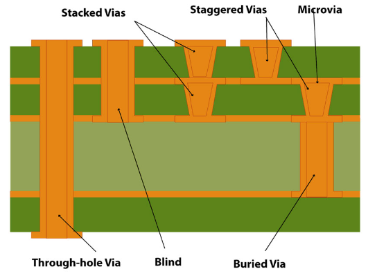
HDI PCBs rely on several types of vias to achieve their high-density interconnections. Each type of via has its specific role in the design and manufacturing process.

Blind Vias
Blind vias connect an outer layer of the PCB to one or more inner layers but do not extend through the entire board. These vias allow for complex routing without using unnecessary space on the PCBās inner layers.
Buried Vias
Buried vias are located entirely within the board, connecting internal layers without appearing on the outer surfaces. This is ideal for designs where surface area needs to be preserved for components, while still allowing inter-layer connectivity.
Microvias
Microvias are tiny vias, typically created using laser drilling, that connect adjacent layers of the PCB. These are essential for HDI designs as they save space while maintaining high-density connections. They can be used in stacked or staggered configurations to optimize space and signal flow.
Staggered Vias
Staggered vias are microvias that are offset from each other across layers. This design allows for more flexibility in routing and avoids overlapping, making it a popular choice for HDI PCBs that require complex routing.
Through Hole Vias
Though not exclusive to HDI designs, through-hole vias extend through the entire PCB, connecting all layers. While these vias occupy more space, they are sometimes necessary for power connections or when working with thicker boards.
What is the Difference Between PCB and HDI PCB?
The key difference between a traditional PCB and an HDI PCB lies in the design and manufacturing process. Traditional PCBs use through-hole technology and thicker traces, limiting the board’s ability to accommodate high-density components. HDI PCBs, by contrast, use finer lines, smaller vias, and advanced interconnect techniques to maximize component density. Here are some key differences between them:
Manufacturing Processes
The embedded via and blind via technologies used in the manufacturing process of HDI (High-Density Interconnect) boards allow for the addition of more layers without increasing the thickness of the board, thereby improving space utilization. In contrast, the drilling process for standard PCBs is relatively simple, but as the number of layers increases, the board thickness also increases accordingly. This difference means that HDI boards require more advanced equipment and higher technical requirements during production.
Space Constraints
In space-constrained devices, such as smartphones and portable electronics, HDI boards are the ideal choice because they can integrate more functions within a smaller size. HDI boards can achieve a line width of 2/2 mil and a 10-layer board thickness of below 0.8mm. Standard PCBs, due to their larger size and lower integration, may not be suitable for these applications. The line width and spacing of regular PCBs are generally limited to 3/3 mil, and their thickness also has certain restrictions.
Performance Requirements
For high-end electronic products that require high-speed signal processing and complex circuit designs, HDI boards offer better performance. Due to their high density and efficiency, HDI boards can meet the high-performance demands of modern electronic devices. Standard PCBs, on the other hand, may not be suitable for these applications because of their lower signal transmission quality and higher latency.
Different Layering Methods
HDI boards are created through continuous stacking and lamination, resulting in advantages such as being “light, thin, short, and small.” Electrical interconnections between layers are achieved through conductive vias, embedded vias, and blind vias, making the structure different from standard multilayer boards. Most HDI boards are laminated two or more times (except for special structures), while standard boards are typically laminated once.
PTH vs. HDI PCB
Plated Through Hole (PTH) technology is commonly used in traditional PCBs and involves drilling holes through the entire board to connect different layers. This method, while reliable, is limited in terms of design flexibility and component density.
HDI PCBs, on the other hand, use smaller vias such as microvias, blind vias, and buried vias. These allow for more efficient use of space, making HDI technology the go-to solution for high-density, multi-layer designs.
High Density Interconnect PCB Applications
- Communication equipment
- Computers and servers
- Automotive electronics
- Medical equipment
- Industrial control equipment
- Consumer electronics
- ADAS system
- Wireless connection module
For nearly 20 years, Best Technology have always been committed to providing overseas customers High Mixed, Low Volume products with Reliable Quality and Quick Delivery, and are determined to become one of most trusted partners in the field of printed circuit boards and PCBA. As an expert of HDI PCB manufacturer, we are so confident that we can provide the highest quality product that highly meet your specifications.


