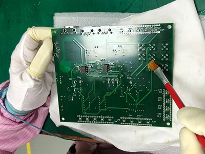
pcb
Home > Blog

Archive for the ‘Chinese Holiday’ Category

Can you use AC in PCB?
Monday, October 7th, 2024

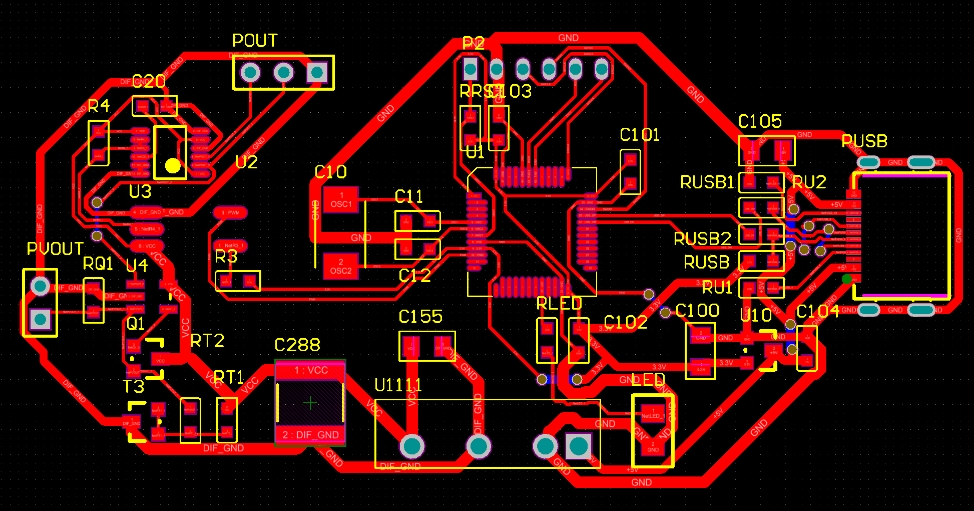
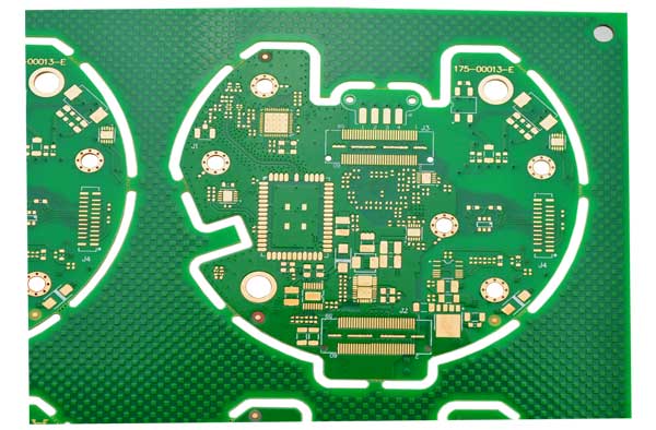
Can you use AC in PCB?AC can be used in PCB boards. PCB boards are designed to support the use of AC, and the functions of AC can be realized through proper circuit design and component selection.
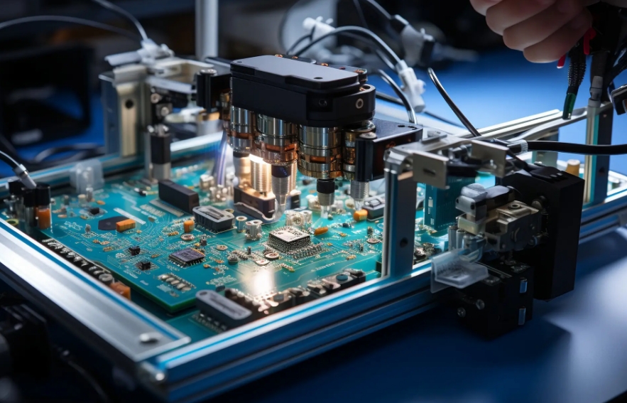
Can you use AC in PCB?

Can you use AC in PCB?

The use of AC in PCB boards requires consideration of the characteristics of AC. The current magnitude and direction of AC change continuously over time, which requires the components and layout on the PCB to adapt to such changes. For example, components such as inductors and capacitors play an important role in AC circuits, and their parameters and layout need to be carefully designed to achieve the desired circuit performance.

Specifically, AC circuit design on PCB boards includes selecting appropriate components, layout, and routing. For example, using test instruments such as LCR digital bridges can measure the parameters of components in AC circuits to ensure that the performance of the circuit meets the design requirements. In addition, reasonable ground routing and layout can reduce signal interference and ensure the stable transmission of AC.

Is the circuit board DC or AC?

Circuit boards can transmit both direct current and alternating current. In modern electronic products, we use alternating current for power supply, so most circuit boards are also designed to transmit alternating current. Of course, in some special application scenarios, some circuit boards also need to transmit direct current. Whether transmitting direct current or alternating current, the circuit board needs to meet the requirements of the transmitted current.
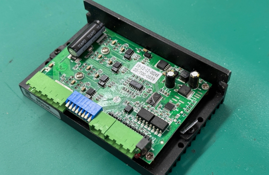
Is the circuit board DC or AC?

What is the PCB in AC?

The alternating current in PCB refers to the current whose direction changes periodically, that is, alternating current (AC). The application of alternating current in PCB is mainly reflected in power conversion and power transmission. PCB power supply usually converts AC into stable direct current (DC) output to meet the demand of electronic equipment for stable power supply. PCB power supply converts AC into the required DC through components such as transformers, rectifiers, filters and voltage regulators, and provides stable power output.

How to calculate the bandwidth of AC in PCB traces

The calculation of AC PCB trace width can be performed by the following formula: W = (I / J) * K, where W represents the trace width, I represents the current, J represents the current density, and K represents a coefficient related to materials and processes. ‌This formula shows that the trace width is related to the current, current density, and material properties‌.

AC in PCB Design Guide

AC in PCB Design Guide

Current Carrying Capacity: The width of a trace directly affects its ability to handle current without exceeding temperature limits or causing excessive voltage drop.
‌Impedance Control: In high-frequency applications, maintaining controlled impedance is critical for signal integrity. Trace width, trace spacing, and dielectric properties affect the characteristic impedance of the transmission line.
‌Heat Dissipation: Adequate trace width helps to effectively dissipate heat, preventing thermal issues such as trace delamination or solder joint failure.
‌Voltage Drop: Narrower traces exhibit higher resistance, resulting in increased voltage drop along the length of the trace. By adjusting the trace width, the voltage drop can be minimized.
‌Manufacturability: The PCB manufacturing process imposes restrictions on the minimum trace width, and designers must balance performance requirements with manufacturability constraints. ‌2.
‌Minimum Trace Width: Most manufacturers have a minimum trace width of 6mil or 0.152mm, and typically use traces of 0.254-0.3mm.
‌Material and Process Deviations: Due to the possibility of material and process deviations in the actual PCB manufacturing process, a certain margin needs to be left when calculating the line width.
‌Signal Integrity Simulation‌: Perform signal integrity simulations to ensure impedance is controlled and signal degradation due to reflections, crosstalk, or transmission line effects is minimized‌

AC in PCB wiring

The current trend is that the power supply voltage is getting lower and lower (especially for highly integrated digital devices), the space occupied is getting smaller and smaller, the weight is getting lighter and lighter, and the efficiency is getting higher and higher, which requires the precise design of the power supply circuit starting from the PCB.
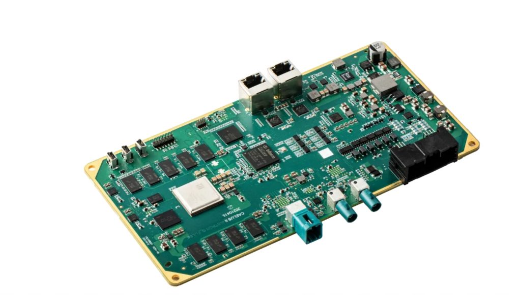
AC in PCB wiring

Safety distance includes electrical clearance (spatial distance), creepage distance (surface distance) and insulation penetration distance…

  1. Electrical clearance: the shortest distance between two adjacent conductors or one conductor and the adjacent motor housing surface measured along the air.
  2. Creepage distance: the shortest distance between two adjacent conductors or one conductor and the adjacent motor housing surface measured along the insulation surface.

Determination of electrical clearance:

The distance can be determined according to the measured working voltage and insulation level

The electrical clearance size requirements of the primary side line are shown in Table 3 and Table 4

The electrical clearance size requirements of the secondary side line are shown in Table 5

But usually: Primary side AC part: L-N ≥ 2.5mm before the fuse, L.N PE (earth) ≥ 2.5mm, no requirements are made after the fuse is installed, but a certain distance should be maintained as much as possible to avoid short circuit damage to the power supply.

Primary side AC to DC part ≥2.0mm

Primary side DC ground to earth ≥2.5mm (primary side floating ground to earth)

Primary side to secondary side ≥4.0mm, components connected between primary and secondary sides

Secondary side gap ≥0.5mm

Secondary side ground to earth ≥1.0mm

Note: Before determining whether it meets the requirements, the internal parts should be applied with a force of 10N and the outer shell with a force of 30N to reduce the distance so that the space distance still meets the requirements under the worst case.

Determination of creepage distance:

Based on the working voltage and insulation level, the creepage distance can be determined by looking up Table 6

But usually: (1), primary side AC part: L-N ≥2.5mm before the fuse, L.N earth ≥2.5mm, no requirement is required after the fuse, but try to keep a certain distance to avoid short circuit damage to the power supply.

(2) Primary side AC to DC part ≥2.0mm

(3) Primary side DC ground to ground ≥4.0mm such as primary side ground to earth

(4) Primary side to secondary side ≥6.4mm, such as optocoupler, Y capacitor and other components, the foot spacing ≤6.4mm needs to be slotted.

(5) Secondary side parts ≥0.5mm

(6) Secondary side ground to earth ≥2.0mm or more

(7) Transformer two-stage ≥8.0mm or more

  1. Insulation penetration distance:

It should meet the following requirements according to the working voltage and insulation application:

  • For working voltage not exceeding 50V (71V AC peak or DC value), there is no thickness requirement;
  • The minimum thickness of additional insulation should be 0.4mm;
  • When the reinforced insulation is not subjected to any mechanical stress that may cause deformation or performance degradation of the insulating material at normal temperature, the minimum thickness of the reinforced insulation should be 0.4mm. If the insulation provided is used in the protective casing of the equipment and will not be bumped or scratched during maintenance by the operator, and any of the following conditions apply, the above requirements do not apply to thin insulating materials regardless of their thickness;
  • For additional insulation, at least two layers of material are used, each of which can pass the dielectric strength test for additional insulation; or:
  • For additional insulation composed of three layers of material, any combination of two layers of material can pass the dielectric strength test for additional insulation; or:
  • For reinforced insulation, at least two layers of material are used, each of which can pass the dielectric strength test for reinforced insulation; or:
  • For reinforced insulation composed of three layers of insulating material, any combination of two layers of material can pass the dielectric strength test for reinforced insulation.
  1. Points to note about wiring process:

Flat components such as capacitors must be flat without glue.

If the distance between two conductors can be shortened by applying a force of 10N, which is less than the safety distance requirement, glue can be used to fix the part to ensure its electrical clearance.

When laying PVC film inside some shell equipment, attention should be paid to ensuring the safety distance (pay attention to the processing technology).

When fixing the parts with glue, be careful not to leave foreign matter such as glue wire on the PCB board.

When processing parts, insulation damage should not be caused.

  1. Requirements for flame-proof materials:

Heat shrink tubing V-1 or VTM-2 or above; PVC tubing V-1 or VTM-2 or above

Teflon tubing V-1 or VTM-2 or above; plastic materials such as silicone sheets, insulating tape V-1 or VTM-2 or above

PCB board 94V-1 or above

  1. Regarding insulation level

(1) Working insulation: insulation required for normal operation of equipment

(2) Basic insulation: insulation that provides basic protection against electric shock

(3) Supplementary insulation: independent insulation applied in addition to basic insulation to protect against electric shock in case of basic insulation failure

(4) Double insulation: insulation consisting of basic insulation plus supplementary insulation

(5) Reinforced insulation: a single insulation structure that provides the same level of protection against electric shock as double insulation under the conditions specified in this standard

The applicable situations of various insulation are as follows:

A. Operational insulation

a. Between parts with different voltages

b. Between ELV circuits (or SELV circuits) and grounded conductive parts.

B. Basic insulation

a. Between parts with dangerous voltages and grounded conductive parts;

b. Between SELV circuits with dangerous voltages and grounding-dependent;

c. Between the primary power conductor and the grounded shield or the core of the main power transformer;

d. As part of double insulation.

C. Supplementary insulation.

a. Generally speaking, between accessible conductive parts and parts that may carry dangerous voltages after basic insulation is damaged, such as:

â… . Between the surface of handles, knobs, handles or similar objects and their ungrounded axis.

â…¡. Between the metal casing of the second category equipment and the outer skin of the power cord passing through this casing.

â…¢. Between the ELV circuit and the ungrounded metal casing.

b. As part of double insulation

D. Double insulation

Double insulation Reinforced insulation

Generally speaking, between the primary circuit and

a. between accessible ungrounded conductive parts, or

b. between floating SELV circuits, or

c. between TNV circuits

Double insulation = basic insulation + supplementary insulation

Note: ELV circuit: extra low voltage circuit

Under normal working conditions, the AC peak value between conductors or between any conductors does not exceed 42.4V or the DC value does not exceed 60V.

SELV circuit: safety extra low voltage circuit.

A properly designed and protected secondary circuit so that under normal conditions or single fault conditions, the voltage between any two accessible parts, and between any accessible parts and the protective grounding terminal of the equipment (only for Class I equipment) will not exceed the safety value.

TNV: communication network voltage circuit

Under normal working conditions, the circuit carrying communication signals

Difference between direct current and alternating current

‌The main differences between DC and AC include direction and polarity, voltage change, current loss, transformer use, and application scenarios.

‌Direction and polarity:

DC: The direction of the current remains unchanged, and the electrons flow from the positive electrode to the negative electrode.

AC: The direction of the current changes periodically, and the electrons flow back and forth between the positive and negative electrodes. ‌
‌Voltage change:

DC: The voltage remains constant and does not change over time.

AC: The voltage magnitude and direction change periodically over time. For example, the mains is an AC with a sine waveform.

‌Current loss:

DC: Fault losses are relatively small.

AC: There is capacitive current, and there is capacitive current in the transmission line. ‌
‌Transformer use:

DC: The voltage cannot be changed using a transformer.

AC: The voltage can be changed using a transformer, which is suitable for boosting voltage to reduce losses during long-distance transportation.

‌Application scenarios:

DC: Suitable for low-voltage electrical appliances and occasions that require stable current.
‌Alternating current‌: Suitable for household and industrial use, using transformers to change voltage to suit different needs.‌

FAQ About AC in PCB

FAQ About AC in PCB

FAQ About AC in PCB

Q: The relationship between PCB current and line width. Is the current divided into AC or DC?
A: The relationship between PCB current and line width is not divided into AC or DC. In terms of the nature of the lines on the PCB, the lines are all made of copper materials, and both AC and DC can pass. However, how much current can pass depends on the cross-sectional area of ​​the line on your PCB. That is, line width x thickness of the copper foil of the line. If the cross-sectional area of ​​the line is small, only small current signals can pass, and if the cross-sectional area is large, large current signals can pass. This signal can be AC ​​or DC.
Not just 1mm, any line width can pass DC or AC signals.

Q: There is a packaged device, and there are 2 pins in the device that need to be connected to the live wire and neutral wire of 220V AC respectively. So how to deal with this power line when drawing the PCB? Are there any size requirements for pads, wires, etc.? Are there any protective measures required? Is it not possible to directly add pads to connect to the pin pads of the device?
A: It is best to mill a groove between the neutral wire and the live wire, and choose the thickness of the wire according to the current. When the current is large, you can put a tin layer on the wire, and the pad should be slightly larger.

Q: The grounding of the PCB circuit board design is also the negative pole. What is the difference between the grounding here and the AC grounding?

A: The concept of the circuit board ground is somewhat different from that of the power supply system. The power supply system refers to the earth, that is, the terminal with the same potential as the earth.

The ground in the circuit board is just a common terminal of a potential, which can be positive or negative, depending on the needs of the designer. It’s just that everyone is used to and assumes that the negative pole is the common terminal, that is, the ground. The circuit board ground is not necessarily connected to the earth.

But it must be connected to the earth when EMI filtering is required.

Q: Should all GNDs on the PCB board be connected? There is a terminal (screw type) with two terminals marked as V1+ and V1- on the PCB schematic. Should V1- be connected to the power supply ground? But I used a multimeter to measure why V3- is not connected to other GNDs on the board?

So how do you connect the ground and 10V of the power supply to the V1+ and V1- ends of the terminal?

A: Not all ground wires on the board are connected together. The ground wires are divided into analog ground and digital ground, just like the ground wire in DC and the ground wire in AC cannot be connected together. That is to say, there is a ground wire that is specifically used for power supply, and there is a ground wire that is specifically used for signals (shielding signal interference). These two ground wires cannot be connected together.
In addition, you mentioned V1+ and V1-, and V1- should not be considered a ground wire. Generally, the signal represented by this method is a differential signal, that is, the V1 signal is differentially divided into V1+ and V1-, which can reduce external interference and transmit farther. Finally, V1+ and V1- are integrated into the V1 signal.
You need to figure out whether the V1+ and V1- of the terminal are used for power supply. If they are used for power supply, then V1+ is the positive pole. V1- is the negative pole. Since you didn’t show us the picture, you can’t just connect it randomly. The circuit board needs to connect not only power but also signals, depending on how your board is made.

You may also like

Board electronics with holes
Friday, October 4th, 2024

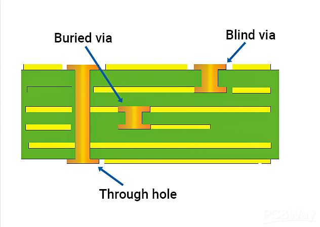
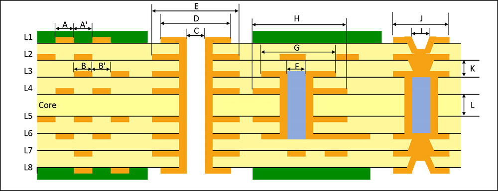
Board electronics with holes The types of vias in PCB include through holes, blind holes and buried holes, which have different characteristics and requirements in design and manufacturing. The selection of the appropriate via type should consider the number of PCB layers, wiring density, signal frequency, cost budget and production process. The via design should pay attention to avoid affecting the welding quality, preventing electrical short circuits, and saving costs in high-density packaging.

What are the holes in a PCB called?

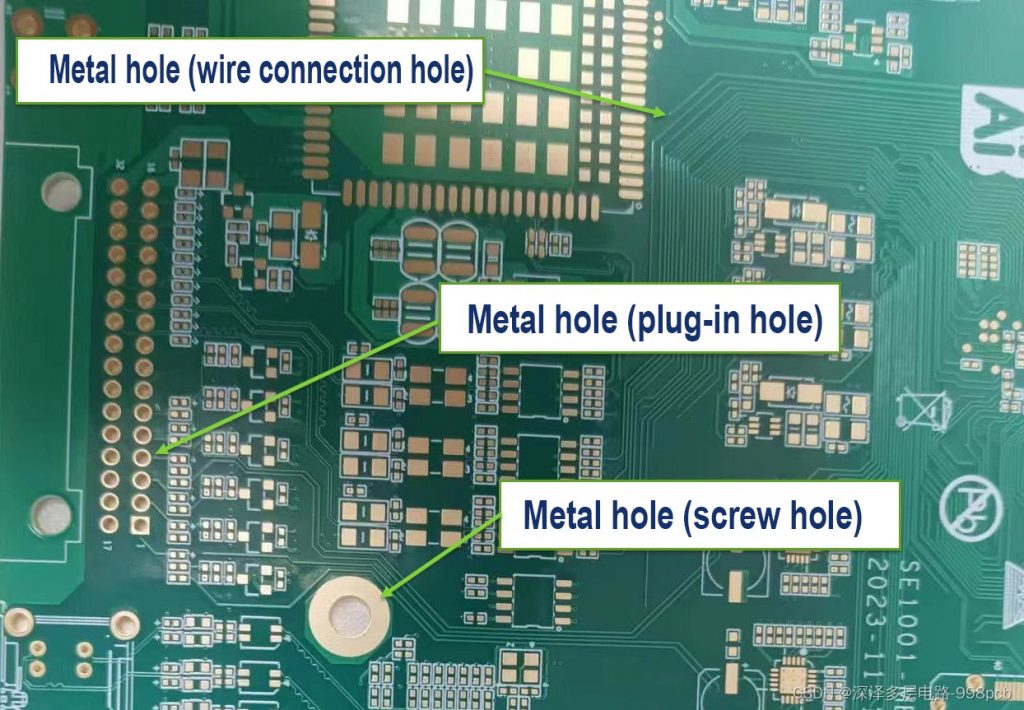
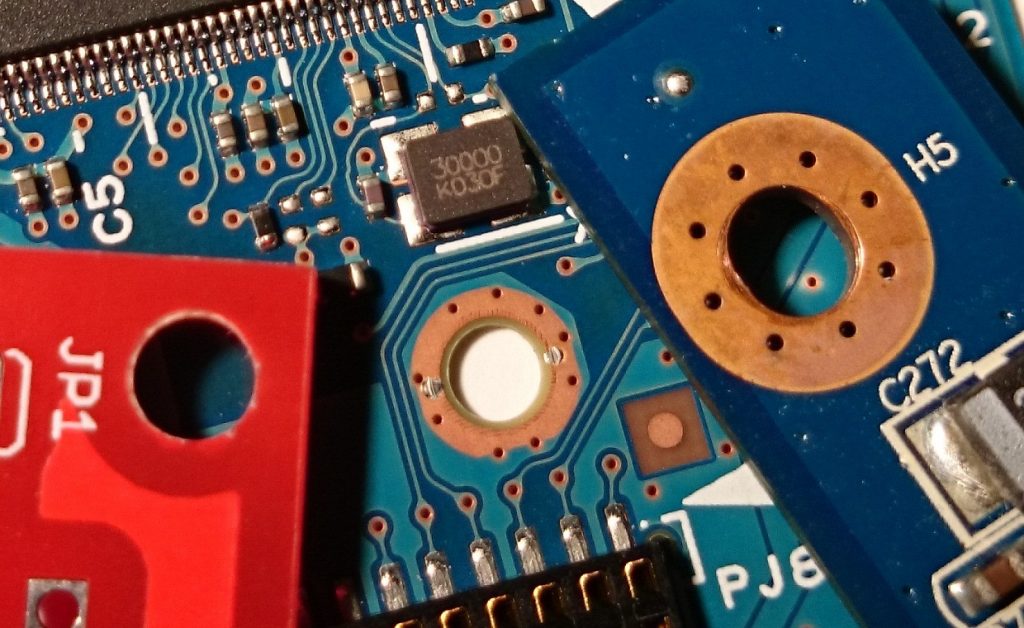
What are the holes on PCB called? What are the holes in the circuit? The holes on PCB can be roughly divided into 3 types, screw holes (mounting holes), conductive holes (vias), and plug-in holes.

Screw holes: Screw holes are used for fixing.

Conductive holes: Conductive holes (also called vias) are used for conducting electricity just like circuits.

Plug-in holes: Plug-in holes are of course used to plug in various parts, such as diodes, transistors, capacitors, inductors, etc.

What is a through hole

What is a through hole? Through holes, also known as perforations, are holes in a PCB that go all the way through the board. Their main purpose is to provide electrical connections for component pins while allowing soldering on both sides of the board.

1.A via is a special through hole whose wall is metallized to achieve electrical connection between different layers on a circuit board. This type of hole is usually used to connect component pins to internal circuits, or to achieve electrical connection between different layers in a multi-layer PCB. Vias need to be metallized during the PCB manufacturing process, which usually includes drilling, desmearing, chemical copper plating, and electroplating.

What is a through hole

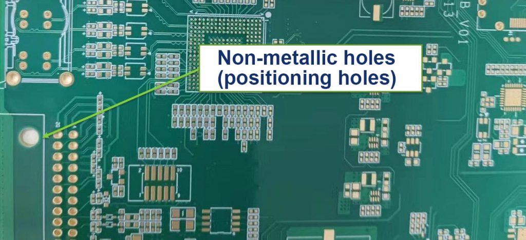
2.Non-conducting holes are the opposite of through holes. Their hole walls are not metallized, so they do not have electrical connection functions. These holes are mainly used for mechanical fixation, heat dissipation or identification purposes. Non-conducting holes are relatively simple in the PCB manufacturing process, and only drilling operations are required.

What is a through hole

What is a blind via?

A blind via is a hole that extends from one side of a PCB to a certain internal layer without penetrating the entire board. The emergence of blind vias is mainly due to the development of HDI technology, which provides circuit designers with greater flexibility and more compact layout. Blind vias are usually used to connect surface mount components (SMD) to internal circuit layers, or to connect circuits between different internal layers.

What is a blind via?

What are buried vias?

Buried vias are holes located inside the PCB that do not penetrate any side of the board. They are completely hidden inside the board and are used to connect circuits between different internal layers. Buried vias are especially useful in HDI boards because they can reduce the overall thickness of the board while maintaining electrical connections between internal circuits.

What is a microvia?

Microvia refers to a hole with a smaller diameter, usually at the micron level. The emergence of microvia technology enables PCB designers to achieve more complex circuit layouts in a smaller space. Microvias are often used in high-density, high-reliability electronic devices such as mobile phones and tablets. The manufacture of microvias requires high-precision drilling equipment and technology to ensure the accuracy and reliability of the holes.

What is a microvia?

What are Mounting holes?

What are Mounting holes?Locking holes are auxiliary holes used in the PCB manufacturing and assembly process to accurately locate and fix the circuit board. They are usually located at the edge or specific position of the PCB to ensure that the circuit board can be accurately aligned and fixed during manufacturing, testing and assembly. The locating holes do not participate in the connection of the circuit, but are essential to ensure the quality and performance of the circuit board.

What are Mounting holes?

What are Mounting holes?

What are thermal vias?

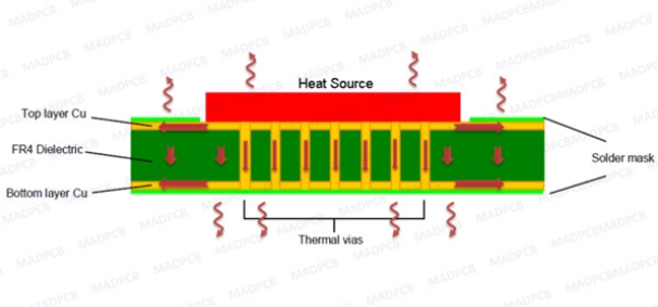
Thermal vias are holes designed specifically for heat dissipation, usually large and can run through the entire PCB or multiple layers. Their role is to reduce heat buildup on the circuit board by increasing surface area and air flow, thereby improving the stability and reliability of the device. Thermal vias are particularly important in high-performance, high-power electronic devices.

What are thermal vias?

FAQ About board electronics with holes

How to solve the contradiction between manual routing and automatic routing of high-speed signals?

Most of the current powerful routing software’s automatic routing tools have set constraints to control the routing method and the number of vias. The routing engine capabilities and constraint setting items of various EDA companies are sometimes very different. For example, whether there are enough constraints to control the winding method of the serpentine, whether the routing spacing of the differential pair can be controlled, etc. This will affect whether the routing method generated by automatic routing can meet the designer’s ideas. In addition, the difficulty of manually adjusting the routing is also related to the capabilities of the routing engine. For example, the pushing ability of the routing, the pushing ability of the via, and even the pushing ability of the routing pair copper. Therefore, choosing a routing tool with strong routing engine capabilities is the solution.

Will adding test points affect the quality of high-speed signals?

As for whether it will affect the signal quality, it depends on the method of adding test points and how fast the signal is. Basically, the additional test points (not using the existing vias (via or DIP pins) as test points) may be added to the line or a small section of wire may be pulled out from the line. The former is equivalent to adding a very small capacitor to the line, while the latter is an additional branch. Both of these situations will have some impact on high-speed signals, and the extent of the impact is related to the frequency speed of the signal and the edge rate of the signal. The magnitude of the impact can be learned through simulation. In principle, the smaller the test point, the better (of course, it must meet the requirements of the test equipment) and the shorter the branch, the better.

Can you introduce some foreign technical books and data on high-speed PCB design?

Now the application of high-speed digital circuits includes communication networks and calculators and other related fields. In the communication network, the operating frequency of PCB boards has reached around GHz, and the number of layers is as many as 40 layers as far as I know. Due to the advancement of chips, the operating frequency of calculator-related applications, whether it is a general PC or server, has reached 400MHz (such as Rambus) or above. In response to the demand for high-speed and high-density routing, the demand for blind/buried vias, mircrovias and build-up process technology is gradually increasing. These design requirements can be mass-produced by manufacturers.

Does the design of rigid-flexible boards require special design software and specifications? Where can I undertake the processing of such circuit boards in China?

Can I use general PCB design software to design flexible printed circuits (Flexible Printed Circuit). The Gerber format is also used for FPC manufacturers to produce. Since the manufacturing process is different from that of general PCBs, each manufacturer will have its own restrictions on line width, line spacing, and aperture (via) based on their manufacturing capabilities. In addition, some copper foil can be laid at the turning point of the flexible circuit board for reinforcement. As for the manufacturer, you can search for “FPC” as a keyword on the Internet and you should be able to find it.

If the size of the circuit board is fixed, if the design needs to accommodate more functions, it is often necessary to increase the routing density of the PCB, but this may lead to increased mutual interference between the routings, and at the same time, the impedance cannot be reduced if the routing is too thin. Please introduce the techniques in the design of high-speed (>100MHz) high-density PCBs?

When designing high-speed and high-density PCBs, crosstalk interference does need to be paid special attention to because it has a great impact on timing and signal integrity. Here are a few things to note:

Control the continuity and matching of the characteristic impedance of the trace.

The size of the trace spacing. The spacing commonly seen is twice the line width. Through simulation, you can know the impact of trace spacing on timing and signal integrity and find the tolerable spacing. The results of different chip signals may be different.

Choose an appropriate termination method.

Avoid the same routing direction of the upper and lower adjacent layers, or even have traces overlapped up and down, because this kind of crosstalk is greater than the case of adjacent traces on the same layer.

Use blind/buried vias to increase the trace area. However, the production cost of the PCB board will increase. It is indeed difficult to achieve complete parallelism and equal length in actual implementation, but it should be done as much as possible.

In addition, differential termination and common mode termination can be reserved to mitigate the impact on timing and signal integrity.

The RF part, IF part, and even the low-frequency circuit part of the outdoor unit are often deployed on the same PCB. What are the material requirements for such PCB? How to prevent interference between RF, IF, and even low-frequency circuits?

Hybrid circuit design is a big problem. It is difficult to have a perfect solution.

Generally, RF circuits are laid out and wired as an independent single board in the system, and there will even be a special shielding cavity. Moreover, RF circuits are generally single-sided or double-sided boards, and the circuits are relatively simple. All of these are to reduce the impact on the distributed parameters of RF circuits and improve the consistency of RF systems. Compared with general FR4 materials, RF circuit boards tend to use high-Q substrates. The dielectric constant of this material is relatively small, the distributed capacitance of the transmission line is small, the impedance is high, and the signal transmission delay is small. In hybrid circuit design, although RF and digital circuits are made on the same PCB, they are generally divided into RF circuit area and digital circuit area, and laid out and wired separately. Shielding is used between ground vias and shielding boxes.

You may also like

National Day Holiday Notice
Saturday, September 29th, 2018

The National Day is around the corner, and everyone will back home or go out for travelling. As usual, we will have a holiday from October 1st, 2018 to October 3rd, 2018. And we will back to work on October 4th, 2018. Therefore, please go ahead or postpone your orders if you have any plans for fabrication. During the holiday, please feel free to contact us at +86-755-2909-1601, or sales@bestpcbs.com with any questions.

We wish you and your family have a wonderful holiday and we thank you for your continued supporting.

Respectfully Yours,

All members of Best

Best, always be your best choice of PCB in China.

You may also like

Chinese Lunar New Year holiday Arrangement
Friday, February 9th, 2018

We’re glad to let everybody know that we’re going to have Chinese Lunar New Year holiday from Feb 10th to Feb 24th and will resume on Feb 25th . As that holiday was in the Spring, so we also named it as Spring Festival, and everybody will back to their hometown to enjoy the longest happy time of the year.

Everybody in our company have worked hard, efficiently, tried every effort to reach our 2017 target. And finally, we have exceeded our personal limitation and got a prosperous 2017.

Now let’s have a good rest, relax ourselves, enjoy the happy time with family, friends. Thanks for their supporting that everybody in our company can work without worrying anything else.

We believe our team will be filled with more fresh energy after resume on Feb 25th. In 2018, let’s see how we can do, what supporting we will do for you, whatever you need is Metal Core PCB, Ceramic PCB, FR4 PCB, Rigid-Flex circuits, or PCBA (SMT) we will always treat you as the VIP of Best Technology, even it is only 1 pcs prototype. Where you are on the Earth, our replies always come in reach you within 12 hours!

You may also like

Ring out the old year 2017 and Ring in the new year 2018
Wednesday, February 7th, 2018

All the guys in Best Technology have worked hard in 2017. Finally, we finished our sales goal successfully. In order to celebrate it and also reward the hard-working staffs, Best Technology hosted a banquet on Jan 28th,2017. Everyone can enjoy the time and have a good rest.

In 2017, The Aluminum PCB sales amount have ranked at the first place compared with the FR4 PCB, Flexible PCB, Ceramic PCB and metal domes. Ms Coco who takes charge of the Aluminum PCB  sales win the champion.

sales win the champion Ms Coco

sales win the champion Ms Coco

At 5 PM, all the staffs attended the evening party. Two beautiful hostesses announced the starting of party. Everyone gave their loudly and warm applaud.

Two Beautiful Ladies

Two Beautiful Ladies

Our CEO Peter who also is our PCB and metal dome sales manager gave a speech. He showed his appreciation for all the staffs, and also sincerely hope everything will be better in the new year 2018.

The CEO`s Speech

The CEO`s Speech

After the CEO’s speech, we started the games.

The Games

The Games

We had a good relax, and forgot the hard and pressure during the games. Everyone has a good recovery with enthusiasm and new energy.

We have a wonderful time in four hours party. Time flies fast. It’s time to take a photo and keep a good memory for this night. Big family, warm and nice.

Took a family picture

Took a family picture

At 9PM, evening party was end. Best Technology hosted a happy and successfully banquet.

2017 has passed, and new year is coming. We will hold hands and work together to provide better service and good quality products for customers.

If any interested about Ceramic PCB, Aluminum PCB, Rigid-flex, Heavy copper PCB, components purchasing and assembly,please feel free to Contact Us. Best Technology will provide our best service and products to our customers.

PCB website: http://www.bestpcbs.com


You may also like

Welcome Back to Office, Welcome to Contact Best Technology
Sunday, February 5th, 2017

Hello Everybody! We had backed to office on Feb 5! (The ninth day of first month of Chinese Lunar Calendar)

It’s a lucky and sunny day! We had 12 people backed to office (excludes people in factory) and according to Chinese culture, number 12 means every month will be lucky and full of successful!

Today one more girl back, tomorrow another guy will back. It’s a normal thing people didn’t back to office on the first day because there’re always something unexpected, such as Wedding, etc. In 2017, we had saw the new baby born of Tiffany’s, wedding party of Hanna, and this year we will see more baby and wedding!

Everybody was so happy to see each other after 2 weeks Spring Festival and eat the wedding candies, as well as checking and replying emails. We have a simple and colorful lunch together and in the afternoon went to Phoenix Mountain Forest for hiking.

Best Technology in Phoenix Mountain Forest

Best Technology in Phoenix Mountain Forest


This is a traditional activity on the first working day after New Year vacation in our company. We can talk to each other under the open air, everybody shared their stories and we always laugh when heard something interested happened during holiday.

Boy and girl with Company Vision

Boy and girl with Company Vision


We believe after such long vacation, all of our team members were fresh with energy and are ready to provide best service and suitable products to our customers. Looking forward to hearing more news from our customers, partners, friends and family, as well as looking for new people to join our team to make their dreams come true!

Happy Girls On Mountain

Happy Girls On Mountain


Best Technology Team Member on top of Phoenix Mountain

Best Technology Team Member on top of Phoenix Mountain


If any enquiry for Printed Circuit board, whatever it is heavy copper PCB (up to 20OZ), or extra thin PCB (0.15mm), Metal Core PCB (1-10 layers), Ceramic PCB, or SMT (PCBA), welcome to contact us. You will see how Best Technology can save your time and money!

You may also like

Chinese Lantern Festival
Monday, February 22nd, 2016

Hello Everyone,

Today is Chinese Lantern Festival,While Chinese people would like to eat sweet dumplings,symbolizing family completely round.After this Festival,the Chinese Spring Festival is end and everyone will start to work hard for the better life.

In ancient times,Chinese people also guess Lantern riddle on this Festival,which is a very interesting game,and GuessGame also need the rich culture of China.

Warm welcome you come to China for Lantern Festival,but don’t worry we will provide some pictures of Lantern Festival if you can not participate in this Time.

Tangyuan-sweet dumpling

Tangyuan-sweet dumpling

Guess-game

Guess Game

Another questions which you may care,today is a Festival but we have no holiday for it,so don’t worry about your orders,we still work even it is Festival today,because Lantern Festival is not a public holiday.So don’t hesitate to send your orders if you would like to order MCPCB,Ceramic PCB,if you would like to know more information pls visit our website:Best Technology Co, Limited

You may also like

Best Technology PCB Team Climbing Team Go Go Go
Monday, February 15th, 2016

Mount-Phoenix,Best Technology will be back again soon….haha,our team go climbing on first working day this Monday,and first pls see the picture who had conquered the Mount-Phoenix,well done!


OK,all the working and orders had got right now so pls let us know if you have anythings we can help,by the way,our company are more and more stronger,we can offer good products and service,don’t hesitate to contact if you have any questions about PCB.

PCB Team from Best Technology Co, Limited

PCB Team from Best Technology Co, Limited

Again,two pictures to show our team in climbing

Go climbing

Go climbing

Best Technology Team on t he top of Mountain

Best Technology Team on t he top of Mountain

After a wonderful vacation, all team members in BestTech are full of fresh energy and will do better in 2016, continue to provide best service, high quality Metal Core PCB, Ceramic PCB, FR4 PCB and other special board to everybody.

You may also like

Chinese Lunar New Year (Spring Festival)
Saturday, January 30th, 2016

We’re glad to let everybody know that we’re going to have Chinese Lunar New Year holiday from Feb 1st to Feb 14th and will resume on Feb 15th (Monday). As that holiday was in the Spring, so we also named it as Spring Festival, and everybody will back to their hometown to enjoy the longest happy time of the year.

Everybody in our company have worked hard, efficiently, tried every effort to reach our 2015 target. And finally, we have exceeded our personal limitation and got a prosperous 2015.

Now let’s have a good rest, relax ourselves, enjoy the happy time with family, friends. Thanks for their supporting that everybody in our company can work without worrying anything else.

We believe our team will be filled with more fresh energy after resume on Feb 15th. In 2016, let’s see how we can do, what supporting we will do for you, whatever you need is Metal Core PCB, Ceramic PCB, FR4 PCB, Rigid-Flex circuits, or PCBA (SMT) we will always treat you as the VIP of Best Technology, even it is only 1 pcs prototype. Where you are on the Earth, our replies always come in reach you within 12 hours!

You may also like

Summer Vacation & Dragon Boat Festival
Tuesday, June 16th, 2015

Waaa, we will have a Summer Vacation in Thailand from June 16th to June 22nd and will back to office on June 23 (Tuesday).


That’s a good relax for everybody in company. And everyone will have more fresh energy after vacation.


Enjoy the working day and thinking of holiday ^_^


Also happy Dragon Boat Festival!

You may also like