Custom LED PCB have revolutionized lighting solutions across industries, offering tailored performance for specialized applications. Let’s explores custom LED PCB from materials to manufacturing processes, helping you make informed decisions for your next project.
At Best technology, we focus on one stop solution PCB solution for custom LED PCB over 18 years. We support ODM and OEM customized LED PCB boards, and we have our own exclusive electronic supply chain, which can achieve low MOQ, multiple varieties, fast delivery, and professional engineers provide free technical services online one-to-one 24 hours a day. Welcome to contact us sales@bestpcbs.com if you have any request for custom LED PCB.
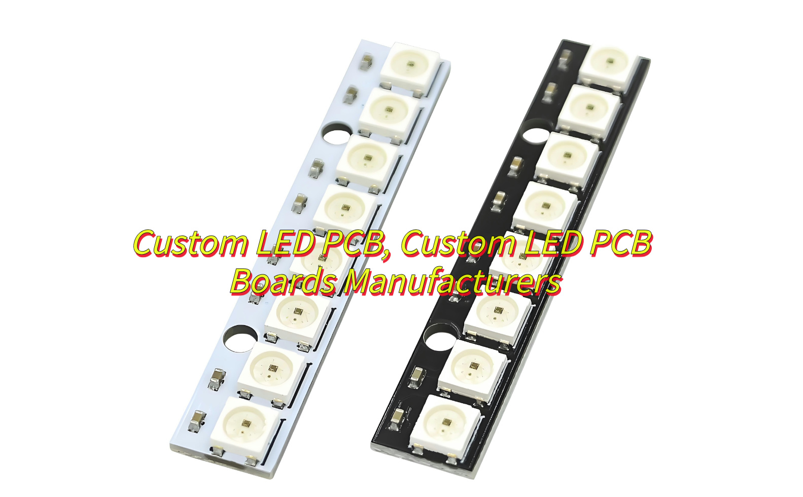
What Is LED PCB?
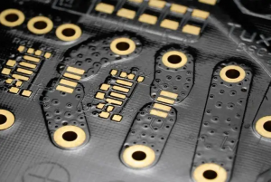
A LED PCB (Light-Emitting Diode Printed Circuit Board) is a specialized board designed to power and control LED arrays. Unlike standard PCBs, these boards prioritize thermal management, high-density layouts, and optical precision to maximize LED performance and lifespan. Custom LED PCBs are engineered to meet specific requirements such as brightness, color temperature, and environmental resilience.
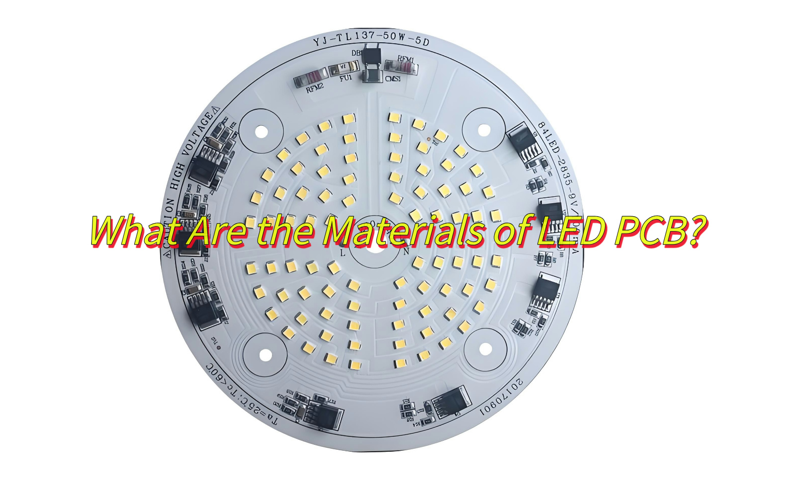
What Are the Materials of LED PCB?
Aluminum Base-Excellent heat dissipation, cost-effective, best for automotive lighting.
FR-4-Low cost, standard insulation, best for Consumer electronics.
Ceramic Base-Ultra-high thermal resistance, best for aerospace systems.
Flexible Base-Bendable, lightweight design, best for wearables, curved displays.
What Are the Advantages of LED PCB?
High Reliability-Withstand extreme temperatures (-40°C to 150°C), humidity, and vibrations.
Superior Thermal Management-Aluminum and ceramic substrates dissipate heat 5-10x faster than FR-4, preventing LED degradation.
Design Flexibility-Custom shapes, sizes, and LED densities (up to 200 LEDs/sq. inch) for unique applications.
Energy Efficiency-Optimized circuits reduce power loss by 15-30% compared to traditional wiring.
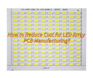
Cost-Effective Scaling-Bulk production cuts costs by 40-60% for large orders.
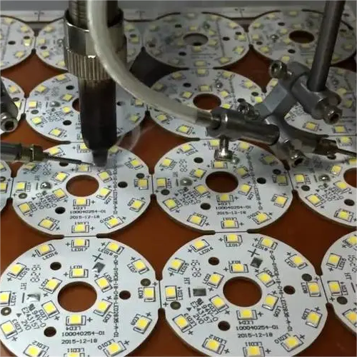
SMT patch: Fully automatic patch machine solders LED chips, resistors, capacitors and other micro components
Surface protection: Coating green oil to protect the circuit to prevent oxidation and solder short circuit.
Surface treatment: Surface spray tin or immersion gold treatment to enhance welding performance and corrosion resistance
Plug-in welding: Manual/mechanical supplementary installation of large-size plug-ins (such as connectors)
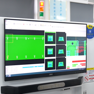
Functional test: Power on to detect LED brightness, color temperature and circuit stability
Final inspection and shipment: Appearance inspection + packaging shockproof treatment
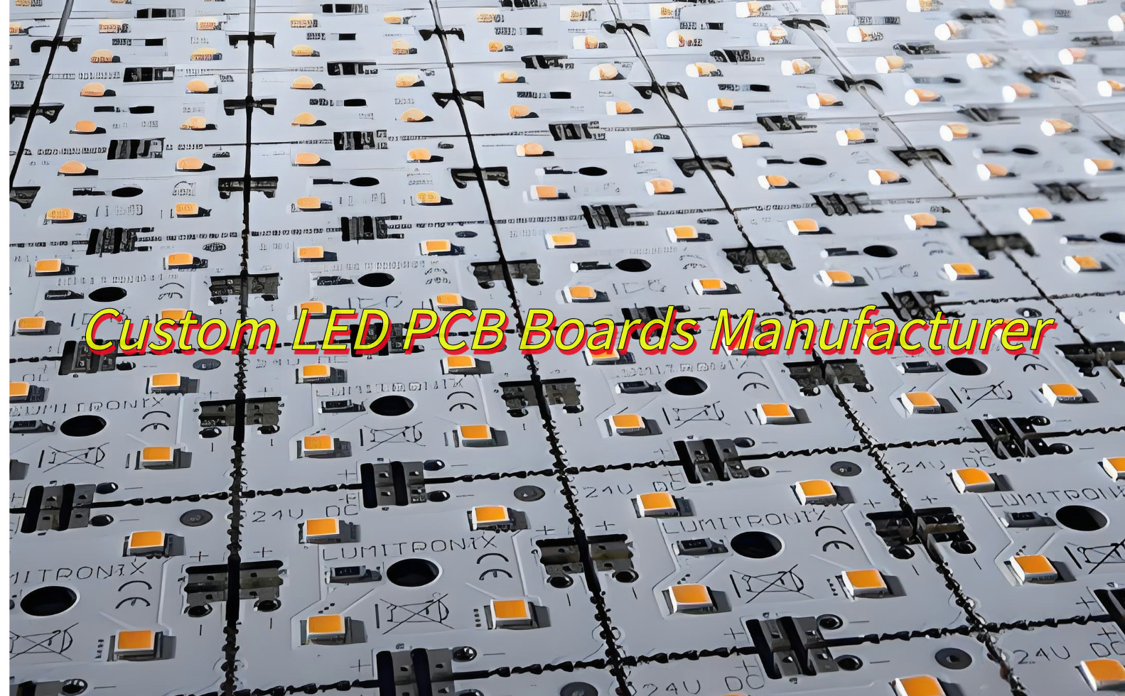
Custom LED PCB Boards Manufacturer
As acustom LED PCB boards manufacturer, Best Technology, establish on June 28, 2006, is a Hong Kong registered company whom focus on custom LED PCB boards manufacturing. We are dedicated to be your best partner of advance and custom LED PCB boards manufacturer. Here are more information about us:
Quality assurance both for our products and before/after-sales service.
Accept small order and mixed order, samples are welcomed.
Discounts are offered base on large order quantities with custom led PCB.
Great variety of LED PCB products with competitive price, welcome OEM and ODM.
Provide expedited custom LED PCB board prototyping service.
If you are interested in our service, welcome to contact us at any time.
FAQs of Custom LED PCB
1.How to improve heat dissipation in custom LED PCBs?
Use aluminum substrates with 2-3 oz copper layers and thermal vias.
2.What’s the minimum order quantity (MOQ) of custom led PCB?
Best Technology accept one piece MOQ for custom led PCB prototyping.
3.Can custom LED PCBs be repaired?
Yes, but rework costs often exceed replacement costs for high-density boards.
4.How much does a custom LED PCB cost?
Price range from $0.50-$20 per piece normal FR-4 board.
5.What’s the lifespan of custom LED PCBs?
Properly designed boards last 50,000-100,000 hours (5-11 years).
To sum up, that’s all about custom LED PCB. Start your project today by partnering with a certified PCB manufacturer to turn your design into reality.
In today’s fast-growing electronics industry, LED (light-emitting diode) technology has become a game-changer in lighting and display applications. LED PCB (printed circuit board) is essential for effectively powering and controlling LEDs. It plays a key role in ensuring the efficiency, lifespan and performance of LED lighting systems.
As the demand for energy-efficient lighting solutions continues to increase, understanding the complexity of LED light PCB design has become critical for engineers, designers and manufacturers. These circuit boards require special manufacturing steps in addition to design guidelines.
What is led light circuit board?
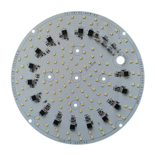
LED light circuit board is the abbreviation of printed circuit board, which is mainly used to carry and connect electronic components of LED lamps. LED light circuit board is usually made of aluminum substrate and FR-4 fiberglass circuit board, where the LED aluminum substrate is printed on the aluminum plane with good thermal conductivity, and then the electronic components are soldered on it. This design helps to improve the heat dissipation performance and stability of LED lamps, and ensure that the LED lamps can work stably for a long time.
The main function of LED light circuit board is to provide power to LED lamp beads and control the brightness and color of its LED lamp beads. In order to light up the LED lamp beads, an LED driving circuit is required, which includes constant voltage driving, constant current driving, PWM driving and other methods, which are usually integrated on the small circuit board of the LED lamp.
In addition, the design and manufacture of the LED lamp circuit board take into account the characteristics of LED, such as long life, high light efficiency, no radiation and low power consumption. Compared with traditional light sources, such as incandescent lamps and fluorescent lamps, LED lamps have significant advantages in efficiency, life and environmental protection.
How to make led light circuit board?
The process of making LED lamp circuit boards involves multiple steps, including welding, self-inspection, mutual inspection, cleaning, friction, wiring, etc.
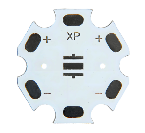
Determine the direction of the lamp: the front side is facing up, and the side with the black rectangle is the negative end.
Determine the direction of the circuit board: the front side is facing up, and the end with two internal and external wiring ports is the upper left corner.
Welding: Carefully weld each solder joint to ensure fullness, cleanness, and no false soldering or leaking.
Self-inspection: After completing the welding, first check whether there is a cold solder joint, leaking solder joint, etc. Use a multimeter to touch the positive and negative terminals of the circuit board to check whether the LED lights are on at the same time.
Mutual inspection: After the self-inspection, it will be handed over to the person in charge for inspection. Only with the consent of the person in charge can it flow into the next process.
Cleaning: Use 95% alcohol to scrub the circuit board to remove residues and keep the circuit board clean.
Friction: Use fine sandpaper (coarse sandpaper if necessary) to grind off the burrs on the edge of the circuit board so that the circuit board can be placed flatly in the fixing seat.
Wiring: Use blue and black thin wires to connect the circuit board. The wiring point close to the inner circle is negative and connected to the black wire; the wiring point close to the outer circle is positive and connected to the red wire. Make sure the wires are connected from the back to the front.
Self-check and mutual check: Check the wiring to ensure that each wire passes through the pad, the length of the wires on both sides of the pad that remain on the surface should be as short as possible, and the thin wires will not break or loosen when gently pulled.
Through the above operations, the production of the LED lamp circuit board can be completed. Each step is crucial, especially the welding and wiring parts. It is necessary to ensure the quality of the welding points and the correct connection of the wires to ensure the normal operation of the circuit board and the normal lighting of the LED lamp.
Why do you need a resistor with an LED?
When using LED, a resistor needs to be connected in series to control the current, prevent excessive current from damaging the LED, and ensure that the LED can emit light normally.
LED is a semiconductor device that can directly convert electrical energy into light energy. Due to its special material properties, LED is very sensitive to current, and excessive or insufficient current may cause the LED to malfunction or be damaged.
Therefore, when the LED is connected to the power supply, a resistor is needed to limit the current to ensure that the LED can work stably and safely.
The main function of this resistor is voltage division and current limiting. It is used to adjust the current passing through the LED to prevent the LED from burning out due to excessive current, while also ensuring that the LED can emit light of appropriate brightness.
Specifically, when current passes through the LED, the resistor will produce a certain voltage drop, thereby reducing the voltage applied to both ends of the LED, thereby controlling the current passing through the LED.
What resistor to use with LED?
Use an LED resistor calculator to help determine the required resistor value.
When using LEDs, in order to protect the LED and ensure its normal operation, it is usually necessary to limit the current by connecting an appropriate resistor in series. This is because each LED has a maximum current value, exceeding which may cause the LED to be damaged.
Using an LED resistor calculator can help you determine the required resistor value to ensure that the current does not exceed the maximum tolerance of the LED.
By entering the relevant parameters of the LED (such as the rated current and voltage), the calculator will automatically calculate the required resistor value to protect the LED from overcurrent damage.
This method is a common practice and is applicable to any situation where a number of LEDs are used in series. In this way, the safe operation of the LED can be ensured while avoiding damage caused by excessive current.
How to improve the heat dissipation performance of LED light circuit boards?
The key to improving the heat dissipation performance of LED light circuit boards is to optimize the heat dissipation path, use efficient heat dissipation materials, and adopt advanced heat dissipation technology.
Optimize the heat dissipation path:
Understanding the heat transfer path of the heat generated by LED components is the first step to improve heat dissipation performance. Heat moves from the LED components through the package wires to the circuit board, and then dissipates through the heat sink.
The heat dissipation efficiency can be effectively improved by using materials with good thermal conductivity, expanding the cross-sectional area of the path (such as using thick copper wire), and applying thermal lubricants to reduce the gaps in the connection parts.
Use efficient heat dissipation materials:
Metals such as copper and aluminum are often used to make heat sinks because of their good thermal conductivity. In addition, new materials such as graphene are also used to make heat sinks because of their excellent thermal conductivity. These materials can significantly improve heat dissipation efficiency.
Adopting advanced heat dissipation technology:
Micro-groove group composite phase change integrated cooling technology is an advanced heat dissipation technology. It effectively removes the heat of high-power electronic devices by changing the closed-circulation cooling medium into a nano-scale water film and utilizing its strong evaporation ability and latent heat exchange ability.
As an excellent thermal conductive medium, thermal conductive silicone grease has excellent electrical insulation and thermal conductivity. It can penetrate into the tiny depressions on the metal surface, increase the contact area, and improve the efficiency of heat conduction from the LED chip to the aluminum substrate.
Are LED PCBs only used in lighting systems?
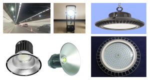
The application range of LED PCB (printed circuit board) is far more than lighting systems. In addition to lighting systems, LED PCB is also widely used in other fields. For example, LED lamps are one of the most common products using LED PCBs. Whether it is home lighting, commercial lighting or outdoor lighting, LED lamps occupy a large market share.
Compared with traditional incandescent lamps and energy-saving lamps, LED lamps have higher luminous efficiency, longer service life and lower energy consumption. They also have features such as dimming and color change, which can meet the needs of different scenarios.
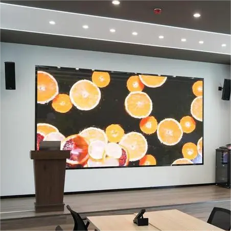
In addition, LED PCB is also used in LED display screens, LED backlight sources and automotive lighting. LED display screens provide high-definition and high-brightness display effects in large-scale events such as sports events, concerts, and exhibitions, bringing a shocking visual experience to the audience.
LED backlight sources have become the mainstream choice in electronic products such as LCD monitors, mobile phones, and tablet computers. Compared with traditional cold cathode fluorescent lamps, LED backlight sources have higher brightness, longer service life and lower energy consumption. At the same time, they can achieve local dimming, improve display effects and reduce energy consumption.
In the field of automotive lighting, with the advancement of automotive lighting technology, more and more cars are beginning to use LED lamps. Compared with traditional halogen and xenon lamps, LED car lights have higher brightness, longer service life, lower energy consumption, faster response speed and better heat dissipation performance, which improves driving safety.
From this we can know that the application of LED PCB is not limited to lighting systems, but is widely used in many fields, including but not limited to lighting, display technology, backlight sources of electronic products, and automotive lighting.
Conclusion:
Designing PCB for LED lights is a complex but critical task that requires careful consideration of various influencing factors, from the selection of manufacturing materials to the testing of thermal conductivity and the quality testing of finished products. Choosing Best Technology has expert design assistance and reliable manufacturing processes, which will allow you to obtain the best results for LED light PCB design.
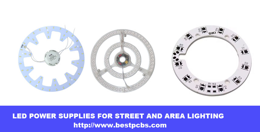
led ring light pcb leads the development of lighting industry with its innovative design, high efficiency and flexibility, bringing more intelligent and comfortable lighting experience to our life.
It is not only an integrated platform of electronic components, but also a perfect combination of modern technology and aesthetics, and is the focus of future lighting trends.
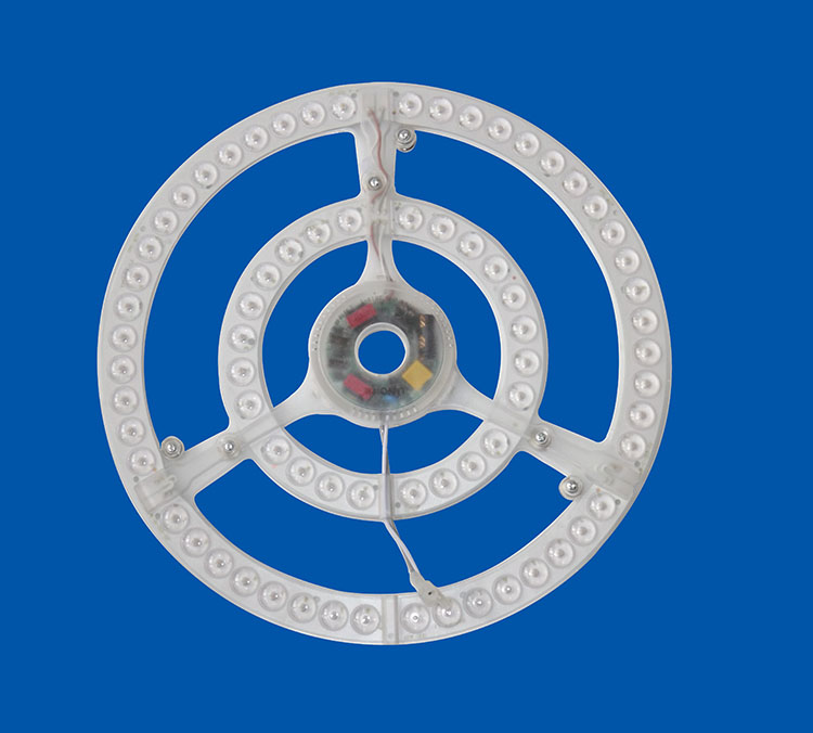
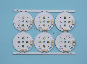
led ring light pcb, like a magic wand on the electronic stage, uses precise SMT technology to lightly attach LED components to it. Whether it is a warm small lamp for home decoration, efficient lighting in commercial space, or smart display inside the car, it is indispensable.
Its core structure includes efficient LED lamp beads, power cords that provide electricity, and intelligent controllers that adjust light effects, which together build an excellent lighting solution.
What Is led ring light pcb
Why use mcpcb for led ring light pcb
With the continuous development of LED technology, the heat generated by LEDs has gradually increased. The traditional FR4 printed circuit board (PCB) has been unable to meet the heat dissipation requirements due to its low thermal conductivity (only 0.36W/m.K). In order to solve this problem, the metal core printed circuit board (MCPCB) was proposed. It attaches the original printed circuit board to a metal with better thermal conductivity (such as aluminum and copper) to enhance the heat dissipation effect. The thermal conductivity efficiency of MCPCB is higher than that of traditional FR4 PCB, reaching 1W/m.K to 2.2W/m.K, which effectively improves the heat dissipation performance of LED PCB.
In addition, the use of MCPCB can also reduce the number of LEDs required to generate lighting, making it an ideal choice for street lights, automotive LED applications, and backlight unit applications. The use of metal substrates has practical advantages in heat dissipation, thermal conductivity, reliability, and electrical insulation, especially in harsh environments, and can also achieve reliable operation of LEDs. For example, using a metal substrate can reduce the LED junction temperature by 20-30°C, improve light output and enhance the overall performance of the product, ensure consistent UV light generation, and expand the possibilities of UV applications in various industries.
Unveiling the Components of LED PCBs
LED Chips: The heart of the LED PCB, these semiconductor chips emit light when current passes through them.
Substrate Material: The base layer of the PCB provides mechanical support and thermal conductivity.
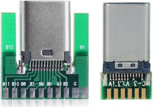
Copper Traces: These conductive pathways connect the LEDs and other components, allowing current to flow through the circuit.
Solder Mask: A protective layer that covers the copper traces, safeguarding them from external factors and preventing short circuits.
Silkscreen: This layer contains markings and labels, providing important information about the PCB’s components and assembly.
Advantages of led ring light pcb?
Thermal performance advantages of metal substrate PCB
High thermal conductivity: The thermal conductivity of metal substrate PCB is much better than that of traditional plastic substrates such as FR4. It can effectively conduct the heat generated by components, reduce the operating temperature of components, and improve the reliability and life of circuit boards.
Good thermal stability: Metal substrate PCB can maintain good dimensional stability and electrical performance in high temperature environment, and is suitable for high temperature working environment.
Mechanical performance advantages of metal substrate PCB
High strength: Metal substrate PCB has high mechanical strength and rigidity, is not easy to deform and break, and can withstand large external forces and vibrations.
Good processability: Metal substrate PCB can be processed by conventional mechanical processing methods such as drilling and cutting, which is convenient for the production of circuit boards with complex shapes and sizes.
Electrical performance advantages of metal substrate PCB Excellent electrical insulation performance: Metal substrate PCB has a special insulation layer design to ensure good electrical insulation performance and avoid electrical short circuits between components.
Low impedance: The conductive layer of metal substrate PCB is made of metal material, which has low impedance, which is conducive to signal transmission and processing.
How does led ring light pcb dissipate heat?
The power device is mounted on the circuit layer. The heat generated by the device during operation is quickly transferred to the metal base layer through the insulating layer, and then the metal base layer transfers the heat to achieve heat dissipation of the device.
Compared with the traditional FR-4, the aluminum substrate can reduce the thermal resistance to the minimum, making the aluminum substrate have excellent thermal conductivity; compared with the thick film ceramic circuit, its mechanical properties are extremely good.
In the circuit design scheme, the heat diffusion is handled very effectively, thereby reducing the module operating temperature, extending the service life, and improving the power density and reliability; reducing the assembly of the heat sink and other hardware (including thermal interface materials), reducing the product volume, and reducing the hardware and assembly costs; combining the power circuit and the control circuit
How to make a LED light circuit board?
Step 1: Design Your LED PCB: Using PCB design software, create a schematic for your LED circuit and design the PCB layout, considering component placement and signal flow.
Step 2: Choose the Materials: Select a suitable substrate material and copper-clad board based on your project requirements.
Step 3: Transfer the Design: Print your PCB layout onto a special transfer paper and transfer it onto the copper-clad board using a heat press.
Step 4: Etch the Board: Immerse the board in an etching solution to remove the excess copper and reveal the copper traces.
Step 5: Drill Holes: Drill holes on the board to accommodate the LED chips and other components.
Step 6: Solder the Components: Carefully solder the LED chips and other components onto the board, ensuring secure connections.
Step 7: Test Your LED PCB: Connect your LED PCB to a power source and test the LEDs to ensure they light up correctly.
How to make a LED light circuit board?
Capabilities of led ring light pcb?
Item
Capabilities
Layer Count
1 – 10 Layers
Max Board Dimension
24*64″(610*1625mm)
Min Board Thickness
0.6mm
Max Board Thickness
4.0mm
Conductor Thickness
0.5oz – 10oz
Min Line Width/Line Space
4/4mil (0.10/0.10mm)
Min Hole Diameter
10mil (0.25mm)
Min Punch Hole Dia
0.12″ (3.0mm)
Min Hole Spacing
16mil (0.4mm)
Min PAD Ring(Single)
3mil (0.075mm)
PTH Wall Thickness
Normal: 0.59mil (15um); HDI: 0.48mil (12um)
Min Solder PAD Dia
14mil (0.35mm)
Min Soldermask Bridge
8mil (0.20mm)
Min BAG PAD Margin
5mil (0.125mm)
PTH/NPTH Dia Tolerance
PTH: ±3 mil (0.075mm); NPTH: ±2mil (0.05mm)
Hole Position Deviation
±3mil (0.075mm)
Outline Tolerance
CNC: ±6 mil (0.15mm); Die Punch: ±6 mil (0.1mm)
Max Aspect Ratio
10:01
Surface Treatment
ENIG, Flash Gold, Hard Gold Finger, Gold Plating(50mil), Gold finger,
Application in medical equipment The rapid progress of medicine is closely related to the rapid development of the electronics industry. Many medical devices are made of basic PCBs alone, such as pH meters, heart rate sensors, temperature measurements, electrocardiographs, electroencephalographs, MRIs, X-ray machines, CT scanners, blood pressure machines, blood sugar level measuring equipment, etc.
Application in industrial equipment PCBs are widely used in manufacturing, especially in industries with high-power mechanical equipment; these devices run on high power and require high current circuit drive. Such as arc welding, large servo motor drives, lead-acid battery chargers, clothing cotton machines, etc.
Application in lighting LED lights and high-intensity LEDs are mounted on PCBs based on aluminum substrates; aluminum has the property of absorbing heat and dissipating it in the air.
Application in the automotive and aerospace industries Flexible PCBs are lightweight but can withstand high vibrations. Because of their light weight, they can reduce the total weight of spacecraft; flexible PCBs can be adjusted even in narrow spaces. These flexible PCBs are used as connectors, interfaces, and can be assembled even in compact spaces
FAQs About led ring light pcb
What is the thermal conductivities and withstanding voltages of BT/FR4 layer and Dielectric layer? The SinkPAD conducts heat primarily through the copper base (400W/m.K), the withstanding voltages of Dielectric layer is around 4KV.
What is the placement accuracy for the SMT components? +/-0.05mm is our SMT accuracy tolerance. You are welcome to come to our SMT factory in Shenzhen China and Vietnam.
Can the aluminum be made as the base of sinkpad MCPCB?
Actually, the sinkpad can only use copper as the base. As you can see the below manufacturing steps, the SinkPad will etch the copper base into convex platform with Copper Etching Solution, then hollow out the Double Layer FR4 PCB, and do lamination with the convex platform. However, regarding of current technical conditions, since aluminum or aluminum alloy cannot directly react with acid, the reaction process is too complex and difficult to control, which will increase the difficulty of etching the LED pad platform. Considering the scrap rate, the process of etching LED pad platform with aluminum is more complex and the overall cost is higher.
Can I plated copper in mcpcb via holes? Generally speaking, copper plating through holes requires hole rings, otherwise the copper in the hole wall will easily fall off.
In addition, if it is a copper substrate, through the hole first to resin plug before copper plating.
Otherwise there’s no chemical reaction between copper and copper. And if the copper layer is connected to each copper layer, it is easy to short circuit.
Are you UL certified led pcb manufacturer?
Yes, we are UL certified manufacturer, our UL is E475635. We have already passed UL certificated. Meanwhile, we are passed ISO9001, ISO13485 and IATF16949 certifications.
Our LED pcbs are manufactured under highly monitored by these quality system controls.
How does the conveity of sinkpad manufactured?
Actually the sinkpad can only use copper as the base.
As you can see the below manufacturing steps, the SinkPad will etch the copper base into convex platform with Copper Etching Solution, then hollow out the Double Layer FR4 PCB, and do lamination with the convex platform.However, regarding of current technical conditions, since aluminum or aluminum alloy cannot directly react with acid, the reaction process is too complex and difficult to control, which will increase the difficulty of etching.