What is a Protoboard?
A protoboard is a basic circuit board used to build and test circuits. It’s also known as a perforated board or perfboard. Unlike breadboards, protoboards need soldering to hold the components. Small holes in a regular grid allow you to place electronic parts wherever you need them. These holes have copper pads or strips to create connections.
Most protoboards are made from phenolic or fiberglass materials. You use wires or solder bridges to link components. This layout is semi-permanent. Once soldered, parts stay in place unless you manually remove them.
Types of Protoboard
Choosing the right protoboard depends on your circuit’s complexity, size, and durability needs. There are three main types commonly used in the industry:
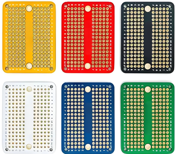
1. Basic Perforated Protoboard (No Copper Tracks)
This is the simplest form of protoboard. It contains only holes arranged in a grid, with no copper pads or tracks. You must manually create all connections using wires or by soldering small jumper wires between components.
2. Stripboard (With Continuous Copper Tracks)
In this version, copper tracks run along rows of holes. These continuous strips form horizontal electrical connections. It saves time because you don’t need to solder as many individual jumpers. However, you may need to break some tracks to isolate sections. This is often done using a drill bit or knife.
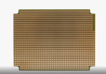
3. Dot Matrix Protoboard (With Isolated Copper Pads)
This type has individual copper pads around each hole, but they’re not connected to each other. You should connect pads manually using wires or solder bridges. It provides better design control than a stripboard and is ideal for compact or complex layouts.
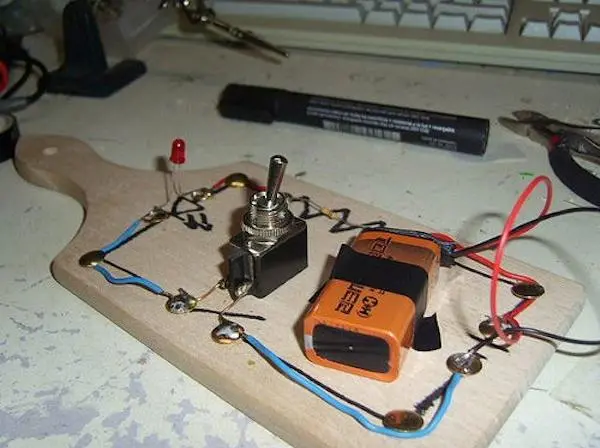
Why Use a Protoboard?
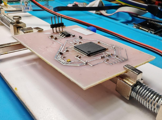
A protoboard is the middle step between a breadboard and a full custom PCB. It’s perfect for making small production prototypes. Once you’re sure the circuit works, the protoboard helps create a more stable version for long-term use.
It offers solid mechanical strength because components are soldered. That’s helpful if you move the board often. You also avoid the loose wires problem that breadboards face. For professional work, protoboards can mimic the actual final board setup better than breadboards.
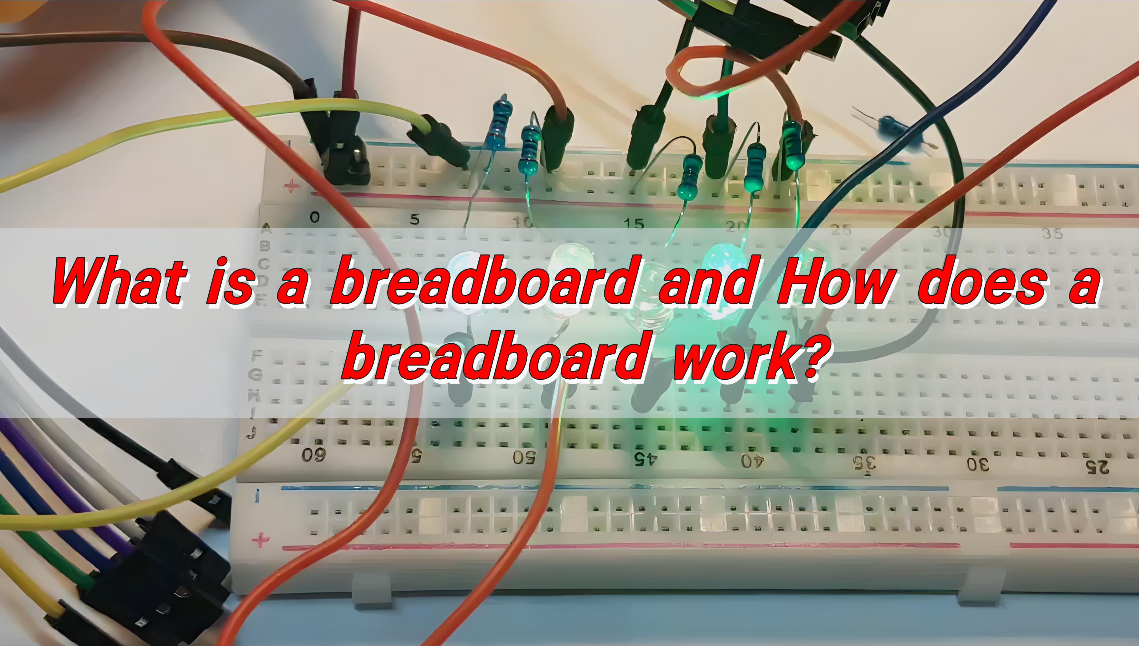
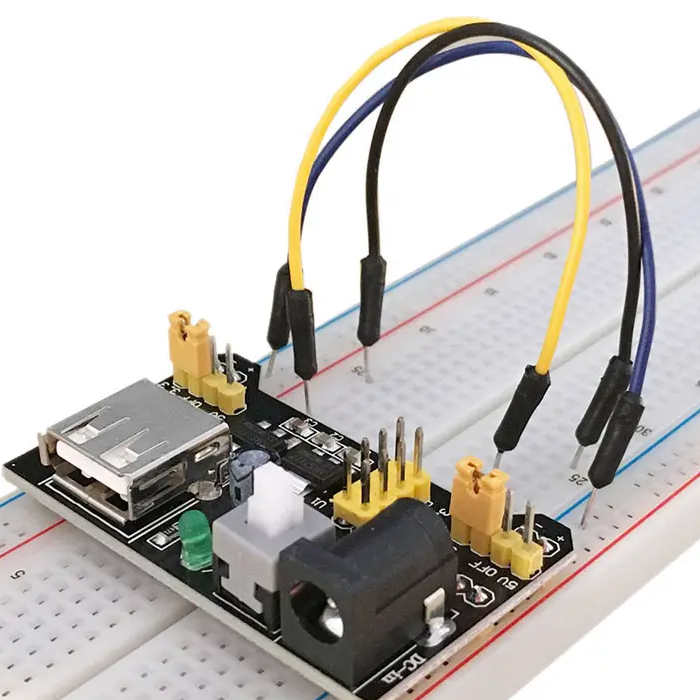
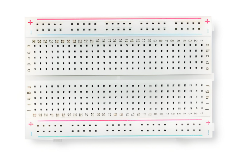
What is a Breadboard?
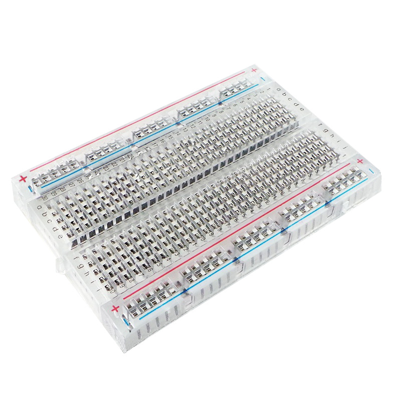
A breadboard is a reusable board used to test circuit designs without soldering. It’s great for beginners, students, and engineers trying new ideas. The name of the breadboard can be traced back to the era of vacuum tube circuits. When the circuit components were mostly large, and people usually connected them by screws and nails on a piece of wood used for cutting the packet, and later the size of the circuit components became smaller and smaller, but the name of the breadboard remained.
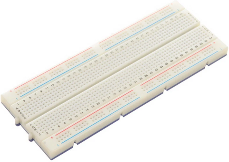
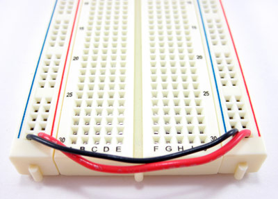
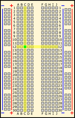
Most breadboards have two power rails on each side. The center area has a grid of holes where you plug in your chips, resistors, or capacitors. You can create and adjust circuits within minutes. That’s why it’s so widely used in electronics labs and classrooms.
Why Do We Need Breadboards?
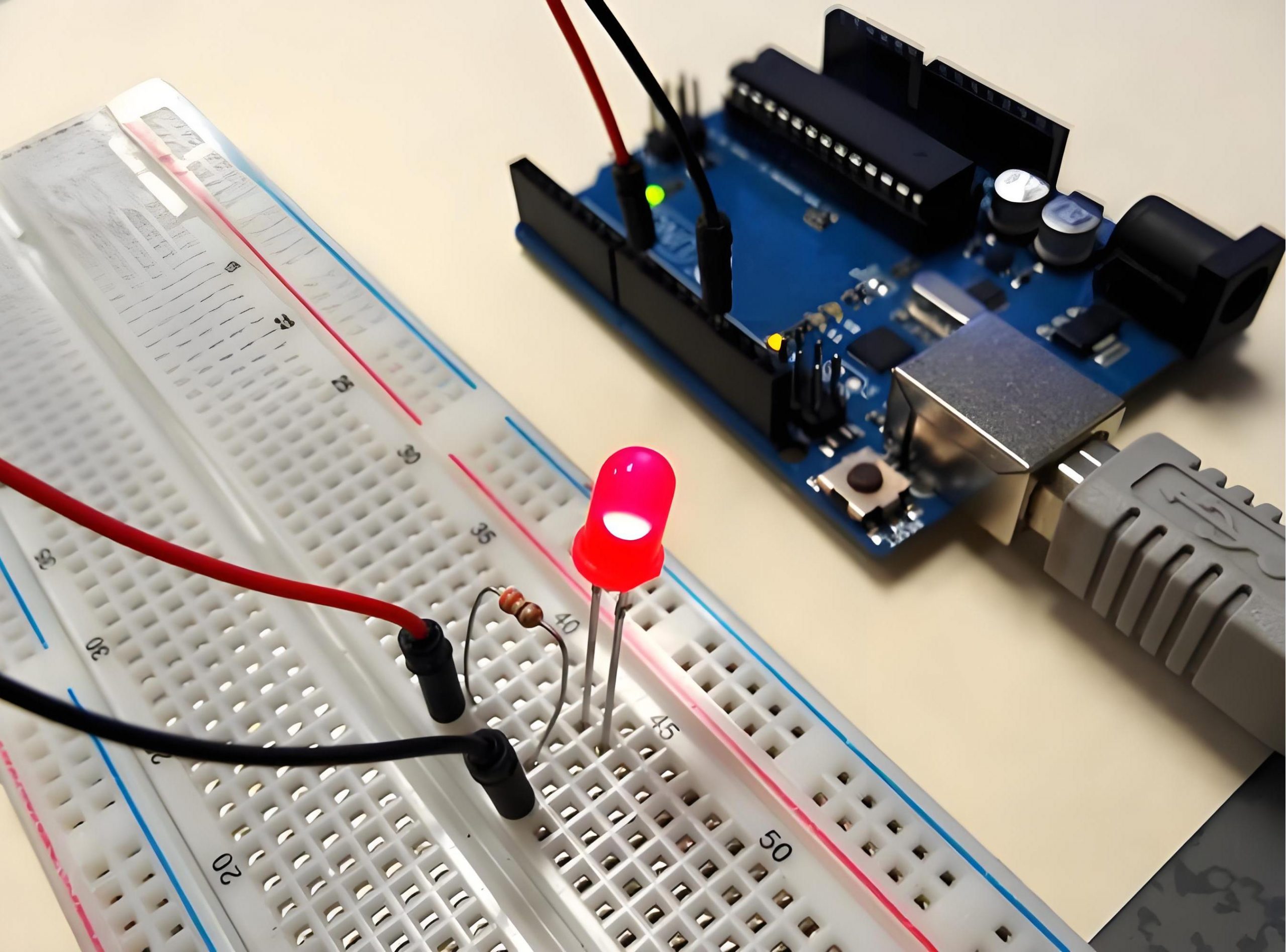
Breadboards are the easiest way to try out new circuits. They let you experiment fast without permanent changes. If something doesn’t work, just pull the wire and try again. This helps reduce time and waste.
They are cost-effective, reusable, and user-friendly. No special tools are needed. Just plug and play. It’s ideal for students learning the basics of electronics. Also, when you’re unsure about a circuit design, the breadboard gives a way to test it before moving forward.
Protoboard vs Breadboard Pros and Cons
Breadboard Pros:
- No soldering needed
- Fast setup
- Easy to reuse
- Great for learning
- Perfect for quick fixes
Breadboard Cons:
- Loose connections possible
- Poor for high-frequency signals
- Can’t handle high current
- Not durable for long-term use
Protoboard Pros:
- Fast design verification
- Handles higher currents
- More stable connections
- Closer to a real PCB layout
- Reduce the cost and risk of mass production
Protoboard Cons:
- Requires soldering
- Hard to change once built
- Takes more time to design
- Not reusable
Breadboards suit fast testing. Protoboards suit semi-final builds or field-ready prototypes before mass production, so it is a bridge between breadboard and PCB.
Protoboard vs Breadboard Cost
In general, breadboards are cheaper if you reuse them. A medium-size breadboard may cost just a few dollars and last for years if handled well. No soldering means it can be used over and over again.
Protoboards are cheaper per unit if you build a permanent prototype. But they can’t be reused after soldering. Some types, like fiberglass protoboards with complex design, they are a bit more expensive. Still, they offer better strength and longer service life. Over time, protoboards become more cost-effective when your goal is a finished design. For simple learning or trials, breadboards are the go-to.
What Is the Difference Between Protoboard vs. Breadboard?
| Feature | Breadboard | Protoboard |
| Soldering Needed | No | Yes |
| Reusability | High | Low |
| Strength | Low | High |
| Cost | Lower (if reused) | Moderate |
| Best Use | Learning & quick tests | Permanent prototypes |
| Current Capacity | Low | Medium to High |
| Circuit Stability | Lower | Higher |
| Changeability | Easy | Hard after soldering |
| Lifespan per circuit | Temporary | Semi-permanent |
| Error Correction | Easy | Difficult |
Both have advantages. Breadboards win in learning environments. Protoboards win in performance-critical situations.
When to Use Protoboard or Breadboard?
Use breadboards when you’re:
- You’re testing a brand-new design
- The project is in an early idea phase
- You’re working on a school or training assignment
- You want to reuse parts later
- You’re building a low-power, low-speed circuit
Use protoboards when:
- You’ve finalized the circuit design
- You need to test the design in a real environment
- The circuit needs to stay assembled for long
- You need stronger electrical contacts
- You’re preparing for PCB production
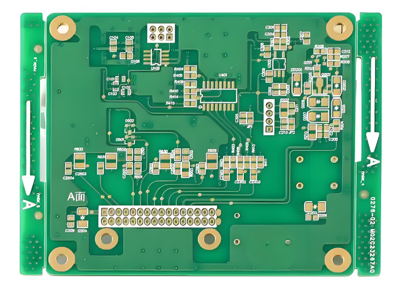
Quick Turn PCBs from Best Technology
Once your prototype works on a breadboard or protoboard, it’s time to go professional. That’s where Best Technology comes in. We totally understand what you want. With over 18 years of PCB manufacturing experience, we turn your final idea into a real, fully functional board.
We specialize in:
- Rapid prototyping
- DFM & DFA analysis support
- Small-batch and mass production
- High-quality material selection
- Fast lead times (1-3days for prototype, 3-7days for mass production)
Whether you’re working with rigid PCB, flexible PCB, aluminum PCB, metal core PCB or ceramic boards, we deliver precision. Our team understands the challenges between idea and product. That’s why we support each stage with reliable service and fast delivery. And when you’re ready to go one step further, Best Technology is always ready to support your quick-turn PCB needs with unmatched precision and care.