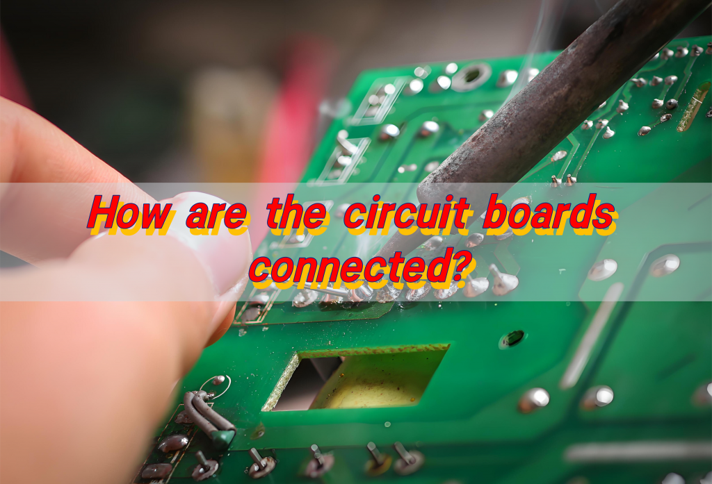
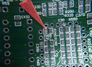
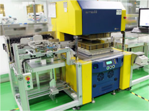
How are the circuit boards connected? Soldering is the most common and long-standing way to connect circuit boards. For traditional circuit boards, we usually use electric soldering irons to perform soldering operations. First, the metal part of the electronic component pins or wires to be connected is tightly fitted with the corresponding pads on the circuit board. Then, the pads and pins are heated with an electric soldering iron, and the solder wire is brought close together to melt the solder and evenly wrap the connection parts to form a stable metal connection.
A circuit board 6 connections typically refers to a design that incorporates six distinct points or pads for electrical connections, which could be input/output ports, signal pathways, or power connections. These boards are often used in simple applications where a limited number of connections are needed to interface with other components or systems.
What are the connections between circuit boards?
The main ways to connect circuit boards include the following:
- Welding connection: This is one of the most commonly used connection methods, which connects components on the circuit board together by welding. The advantages of welding connection are stable and reliable connection, low cost, and suitable for circuit boards that do not require regular changes.
- Plug-in connection: Plug-in connection can achieve fast plug-in and pull-out, easy replacement and maintenance, but requires high precision of plug-ins and sockets, and occupies a large space, which is not suitable for circuit boards with limited space.
- Connector connection: This is a widely used circuit board connection method that can connect circuit boards of different forms and sizes. The advantages of connectors are convenient and fast connection, high reliability, and a large number of plug-in and unplug times, which are suitable for various circuit board application scenarios.
- Plug-in connection: widely used in complex instruments and equipment, and connected through standard pins or sockets. This method is easy to replace and repair, ensuring the reliability and production efficiency of the connection.
- Special connection methods: including V-cut and copper foil bridge connection, spring connection and spring connection, panel connection, etc. These methods are suitable for specific scenarios and needs, such as V-cut for the separation stage of PCB boards, spring connection and spring connection for the connection of flexible circuit boards, and panel connection for multiple PCB designs placed on a large substrate.
How to connect components on PCB?
There are usually the following ways to connect components on PCB:
- Soldering: This is the most common connection method. By connecting the pins of the components to the pads on the PCB with solder, you can use a soldering iron or SMT equipment for soldering.
- Spring contact: For some components that need to be replaced frequently, such as batteries, you can use spring contact to make the components easy to disassemble.
- Screw fixing: For components that need to withstand large forces, such as heat sinks, motors, etc., screw fixing can be used. Pay attention to choosing the right screws and tightening strength.
- Clamping with pliers: For some components that need to be fine-tuned, such as rheostats, potentiometers, etc., pliers can be used to clamp.
- Plastic bayonet: For some components that need to be frequently plugged and unplugged, such as wire connectors, plastic bayonet can be used for connection.
How to connect PCB boards together?
To connect PCB boards together, you can consider the following common methods:
Welding:
- PCB wire welding: This is a simple and commonly used method to achieve connection by directly welding the wire to the pad of the PCB board. When welding, you need to pay attention to the quality and stability of the welding to ensure the reliability of the connection.
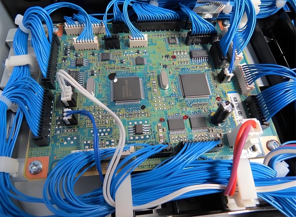
- PCB cable welding: It is suitable for situations where multiple wires need to be connected. You can use cable to connect multiple PCB boards together, and then fix the connection between the cable and the PCB board by welding.
- Direct welding between PCBs: This method is often used for connections between two PCB boards at a 90-degree angle. When welding, attention should be paid to the alignment and fixation between the two PCB boards to ensure the quality of welding.
Plug-in connection:
- Printed circuit board socket: This connection method is often used in more complex instruments and equipment. A printed plug is made from the edge of the PCB board. The plug part is designed according to the size of the socket, the number of contacts, the distance between contacts, the position of the positioning holes, etc., so that it matches the dedicated PCB printed circuit board socket.
- Standard pin connection: This method is suitable for use in small instruments. Two PCB boards are connected by standard pins. The two PCB boards are generally parallel or vertical.
- Crimping: The PCB board is crimped with other components through a special crimping tool to achieve connection. This method is suitable for situations where frequent disassembly and replacement are required.
- Bonding: Use glue or adhesive to bond the PCB board with other components. This method is suitable for situations where the connection strength requirement is not high.
- Use connectors: Connectors are a component specially used to connect PCB boards, which can provide reliable connection and convenient disassembly. There are many types of connectors, and you can choose the right connector according to specific needs.
- Screw fixing: For some larger or heavier PCB boards, screws can be used to fix them to other components to ensure the stability of the connection.
What are the different types of PCB connectors?
The main types of PCB connectors include the following categories:
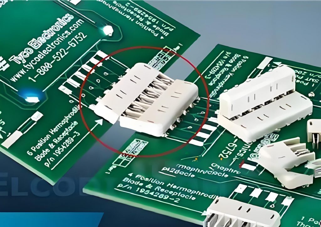
- Ordinary board-to-board connector: used to connect two parallel or vertical PCBs, suitable for signal transmission between different circuit boards. According to different spacing, it can be divided into 0.50mm, 0.60mm, 0.80mm and other specifications. The smaller the spacing, the more pins can be accommodated, and the signal transmission is more intensive, but the processing accuracy and installation requirements are higher.
- Mezzanine connector: mainly used to connect two PCBs with close spacing when space is limited. It is usually connected in a stacked manner to save space and is often used in the connection structure of the motherboard-daughterboard.
- Backplane connector: a group of electrical connectors parallel to each other, each pin of each connector is connected to the same relative pin of all other connectors to form a connector bus.
- Spring-type board-to-board connector: contains a spring structure inside, which can ensure a stable connection even when the spacing between the boards fluctuates. It is suitable for devices with high requirements for connection stability.
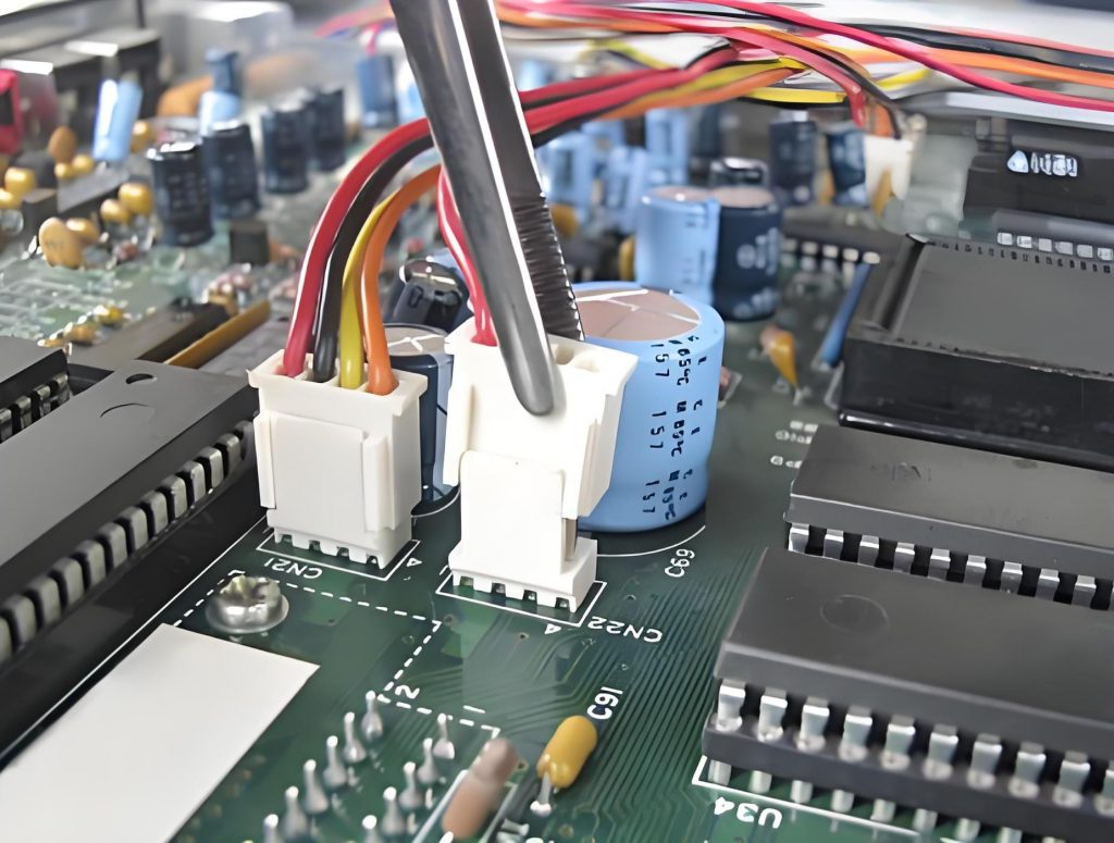
- Wire-to-board connector: used to connect wires or cables to PCBs. The wire connection part is similar to the wire-to-wire connector, while the circuit board connection part is mostly a two-piece connector that is press-fit or welded.
- Wire-to-wire connector: used to connect two wires. One end of the connector is permanently connected to the wire, and the other end forms a detachable interface. Permanent connection methods can use crimping or insulation displacement contacts (IDC), etc.
How to choose PCB connectors?
There are several key factors to consider when choosing PCB connectors:
- Connector type: choose the appropriate connector type according to application requirements.
- Size: The size of the connector needs to adapt to the size and layout of the circuit board to ensure that the connector can be properly installed and connected.
- Electrical performance: consider the rated voltage, rated current, and withstand voltage of the connector to ensure that it can withstand the electrical load required by the device.
- Mechanical performance: includes the number of plug-in and unplugging times, durability, and shock resistance. If the device needs to frequently plug and unplug the connector, a durable and long-life connector should be selected; if the device will be subject to vibration or shock, a connector with good shock resistance should be selected.
- Environmental conditions: Environmental conditions have a great impact on the choice of connectors.
- Technical parameters: Understand the technical requirements of the application, including pin spacing, soldering method, rated voltage, rated current, number of plug-in and unplug times, temperature range, board spacing, connector geometry, and solder hole diameter of the solder tab.
How do you connect wire to a circuit board?
Soldering is usually used to connect wires to circuit boards. Solder the ends of the wires to the pads on the circuit board using a soldering iron and solder.
- Prepare tools and materials: soldering iron, solder wire, flux, wires, and circuit boards.
- Clean wires and circuit boards: Use alcohol or other cleaning agents to clean the wires and pads on the circuit board to ensure a good solder connection.
- Strip the wire: Use wire strippers or scissors to strip a section of the wire end to expose the metal wire inside.
- Tin the wire: Place the end of the wire on the soldering iron tip and wrap it with solder wire at the same time to evenly coat the end of the wire with a layer of solder.
- Solder wires to circuit boards: Place the tinned wire ends on the pads on the circuit board, and use a soldering iron to melt the solder to connect the wires to the pads.
- Check welding quality: Check whether the solder joints are firm and whether there are problems such as cold solder joints or short circuits.
- Clean the soldering area: Use alcohol or other detergents to clean the soldering area to remove excess solder and flux.
Circuit board connection is a technology that requires both theoretical knowledge and practical experience. From basic soldering and plug-in connections to various unique ways of PCB connection, each connection method has its applicable scenarios and key points. Regardless of the connection method, preparation before connection, detailed control during the connection process, and detection and debugging after connection are all crucial.


