pcb
Home > Blog

Posts Tagged ‘copper thickness’

All about copper printed circuit board
Friday, September 27th, 2024

Copper can be said to be an indispensable element in printed circuit boards. In printed circuit boards, copper is used as a conductive line to connect electronic components and realize the function of the circuit. Compared with other conductive materials, copper has a lower resistance, which can reduce the loss of electric energy and improve the efficiency of electronic equipment.

Why is copper used in printed circuit boards?

The main reason for using copper in printed circuit boards is that copper has good conductivity, which can greatly improve the conductivity of the circuit board and ensure that the connection between various components is more stable and reliable.

All about copper printed circuit board

‌In addition, copper foil itself has high mechanical strength and stability, which can effectively prevent the printed circuit board from being damaged or deformed by the external environment.

In terms of high-frequency signal transmission, copper plating can effectively improve the conductor characteristics and impedance matching characteristics of the circuit board, protect the circuit board from oxidation or corrosion, thereby extending the service life of the circuit board and ensuring its stability and reliability.

Copper plating can reduce the voltage drop in the circuit, thereby improving the efficiency of power supply. In addition, copper plating can also enhance the mechanical strength of the PCB, so that it will not deform as much as possible during the welding process, improve the yield rate in the production process, and reduce circuit failures caused by deformation.

However, copper plating also has its disadvantages. For example, when soldering or repairing PCB samples, it may cause difficulty in replacing devices due to excessive heat dissipation, especially in the case of large devices. In addition, in RF circuits, copper plating may cause impedance mutation of the antenna, seriously affecting signal transmission.

How thick is the copper on a printed circuit board?

The thickness of copper foil on a printed circuit board is usually between 18μm and 70μm, but the specific thickness depends on the purpose of the circuit board, the voltage and current of the signal.

The most commonly used copper foil thickness is 35μm, because the copper foil thickness of 35μm is suitable for most application scenarios. However, for applications that need to carry higher power or higher current, such as high-power LED lights, power supply circuits, etc., 2OZ (about 70μm) or thicker copper foil may be selected to ensure the performance of the circuit board and the reliability and stability of electronic products.

In addition, the copper thickness of the circuit board is also affected by the thickness of its substrate. For example, the composite copper foil thickness on a substrate less than 1mm thick is about 18μm, while a copper foil thickness of 55μm may be used on a substrate greater than 5mm.

How do you choose PCB copper thickness?

When choosing PCB copper thickness, you need to consider multiple factors to ensure the performance, cost and production feasibility of the circuit board.

  • ‌Application scenarios of circuit boards‌: For applications that need to carry high power or high current, you may need to choose thicker copper foil to ensure the stability and reliability of the circuit board‌. For general signal transmission, 1oz copper thickness is usually sufficient‌.
All about copper printed circuit board
  • ‌Number of layers and design of circuit boards‌: The inner layer of multilayer boards generally uses 1/2oz and 1/3oz copper thickness, while the outer layer uses 1oz or 1/2oz copper thickness‌.
  • ‌Cost and process requirements‌: The thicker the copper foil, the higher the production cost. Therefore, it is necessary to consider cost factors while ensuring performance‌.
  • ‌Special requirements‌: In some special application scenarios, such as when the circuit board needs to dissipate heat, copper foil with higher thermal conductivity should be selected to enhance the heat dissipation capacity of the circuit board‌.

What is the difference between 1 oz and 2 oz copper PCB?

The main difference between 1 oz and 2 oz copper PCB lies in the thickness of the copper foil and the current load it can withstand. ‌

  • ‌Copper foil thickness‌: 1 oz copper thickness refers to 1 ounce of copper per square foot on the circuit board, while 2 oz copper thickness refers to 2 ounces of copper per square foot.
  • ‌Application scenario‌: 1 oz copper thickness PCB is the most common standard and is suitable for most application scenarios. 2 oz copper thickness is suitable for application scenarios that need to carry higher power or higher current.
  • ‌Electrical performance and heat dissipation performance‌: In theory, thicker copper foil can directly reduce the ground resistance by half, and the number of joules of heat generated per unit time during operation will also be reduced accordingly. At the same time, it can more effectively shield the electromagnetic interference between components and wires.

How thick is the copper on a 1 ounce copper PCB?

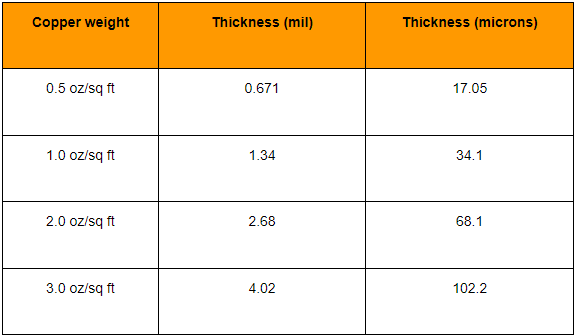
The copper thickness of 1 ounce copper on a PCB is about 35 microns. ‌

In PCB design and processing, the copper thickness is often expressed in ounces (oz) as a unit. Specifically, the thickness of 1 ounce of copper is about 35 microns, which is equivalent to 1.4 mils. Although this method of expression uses the weight unit ounce, it actually indirectly expresses the average thickness of the copper foil through the weight per unit area.
All about copper printed circuit board

In the PCB industry, ounces are not only a unit of weight, but also used to express the thickness of copper foil, where 1oz means the thickness of 1 ounce of copper evenly laid on an area of ​​1 square foot. This method of expression is very common in the fields of electronic engineering and circuit board manufacturing to ensure that the conductivity and current carrying capacity of the circuit board meet the design requirements.

Which metals Cannot be used in printed circuit boards?

In the production of printed circuit boards, some metals are usually not used.

First of all, iron has poor conductivity and cannot meet the requirements of printed circuit boards for good conductive materials. Moreover, iron is easy to rust, which will affect the appearance of the circuit board and may also cause circuit short circuits or poor contact.

Lead is also not suitable for printed circuit boards. On the one hand, lead is a toxic heavy metal. With the improvement of environmental protection requirements, the use of lead-containing materials in the electronics industry is limited, and lead-containing solder in printed circuit boards has gradually been replaced by lead-free solder. On the other hand, lead has poor mechanical properties, low hardness and easy deformation, which may deform or damage the circuit board during manufacturing and use.

Mercury cannot be used in printed circuit boards. Mercury is extremely toxic and has serious harm to the human nervous system, immune system, etc. At the same time, mercury is liquid and volatile at room temperature, difficult to control, easy to cause leakage and pollution, and its conductivity is not ideal.

Although gold has advantages such as good conductivity, corrosion resistance and oxidation resistance, its cost is too high and it is not suitable for large-scale application in printed circuit boards. In addition, gold has low hardness and is easily scratched or worn, affecting the performance and reliability of the circuit board.

What is the major disadvantage of printed circuit boards?

The major disadvantages of printed circuit boards include disposable boards, environmental impact of etching, and compatibility issues. ‌

  • ‌Disposable boards‌: Printed circuit boards are designed with one-time use in mind, which means that if the circuit board needs to be modified after printing, it will not be possible and a new board needs to be created from scratch.
  • ‌Environmental impact of etching‌: The chemicals used in the etching process have a negative impact on the environment. Although the etching process is very effective for circuit board production, it is not environmentally friendly‌.
  • ‌Compatibility issues‌: Before starting to make a circuit board, you need to determine the device you are designing for, which increases the complexity and potential risks of the design‌.

These shortcomings limit the use of printed circuit boards in some applications to a certain extent, especially in scenarios that require high customization or frequent modifications.

In short, copper printed circuit boards occupy an irreplaceable position in the electronics field with their excellent performance. From consumer electronics to communications, automotive electronics, and industrial control, it can be seen everywhere. Copper’s high electrical conductivity, good thermal conductivity, and strong machinability make it a key link connecting the electronic world.

You may also like

The influence of copper thickness on PCB
Monday, August 19th, 2024

Copper thickness has a very important impact on the performance of PCB, and PCBs with different copper thicknesses also have very different applications. The fundamental reason why copper is widely used in circuit board manufacturing is its electrical conductivity, so different copper thicknesses correspond to different electrical conductivities. In addition, copper also has low resistance and thermal stability.

Why fill PCB with copper?

The main purpose of using copper to fill PCB (Printed Circuit Board) is to improve the electrical conductivity of the circuit board, enhance mechanical strength and stability, protect the circuit board from oxidation or corrosion, and improve heat dissipation capabilities. ‌

The influence of copper thickness on PCB

As an excellent conductive material, copper plays a vital role in PCB design. By covering the surface of the PCB with copper foil, the conductive performance of the circuit board can be significantly improved and the connection between various components can be ensured to be more stable and reliable.

Copper foil itself has high mechanical strength and stability, which can effectively prevent PCB from being damaged or deformed due to the influence of the external environment. The corrosion resistance of copper foil can also protect the circuit board from oxidation or corrosion, thereby extending the service life of the circuit board and ensuring its stability and reliability during work.

Since metal has good electrical and thermal conductivity, copper coating can increase the heat dissipation surface area of the PCB, help distribute heat evenly, and prevent the generation of local high-temperature areas. This can not only reduce local heat concentration, but also reduce the temperature gradient of the heat source and improve heat dissipation efficiency.

To sum up, the role of copper-filled PCB is multi-faceted. It can not only improve the conductivity and mechanical stability of the circuit board, but also protect the circuit board from environmental influences, while enhancing the heat dissipation capacity and ensuring the stable operation of electronic equipment. and long-term use‌.

Is a thicker PCB copper better?

The copper thickness of PCB is not as thick as possible, but the appropriate copper thickness needs to be selected according to the design requirements and actual application of the circuit board. ‌

The importance of copper thickness in PCB manufacturing cannot be ignored because it directly affects the conductive performance, heat dissipation performance, mechanical strength and signal integrity of the circuit board. Proper copper thickness can provide good electrical and thermal conductivity while ensuring the reliability and stability of the circuit board.

Although an excessively thick copper layer can improve current carrying capacity and heat dissipation performance, it will also increase cost and weight, which may lead to serious glue flow and increased processing difficulty. Therefore, when selecting copper thickness, factors such as circuit board design requirements, application environment, and cost need to be comprehensively considered.

During the PCB design and manufacturing process, the optimal copper thickness should be selected based on specific application requirements and cost considerations to achieve optimal circuit performance, heat dissipation, and mechanical strength‌.

How thick is the copper on a 1 ounce copper PCB?

The thickness of 1 ounce of copper on a PCB is 35 microns. ‌

The influence of copper thickness on PCB

In the PCB industry, ounces (oz) are the unit used to express copper foil thickness, not weight. Specifically, the thickness of 1oz of copper refers to the thickness achieved by spreading 1oz of copper evenly over an area of 1 square foot.

According to different information, the thickness of 1oz copper can be obtained by different calculation methods, but the generally accepted value is that 1oz copper is equal to 1.4mil (milliinch), which is equivalent to 35 microns. Therefore, whether in international standards or practical applications, the thickness of 1oz copper on PCB is usually considered to be 35 microns.

In addition, the copper thickness of the PCB has a direct impact on the circuit board’s current carrying capacity, heat dissipation, reliability and other performance indicators. Commonly used PCB copper thickness specifications include 1oz, 2oz, 3oz, 4oz, 5oz, 6oz, etc., which correspond to different copper layer thicknesses. The copper layer thickness of 1oz is 35 microns, 2oz is 70 microns, and so on, 6oz is 210 microns. . These specifications provide the basis for selecting different copper thicknesses based on specific application needs to meet different electrical performance and physical requirements.

What is the conventional PCB copper thickness?Thick copper plate, FPC

‌Regular PCB copper thickness is 1oz (35μm). When the thickness of the copper foil reaches or exceeds 2oz, such a PCB board is defined as a thick copper board; for flexible circuit boards (FPC), the copper thickness also has different specifications, for example, 0.5oz copper thickness is used for flexible circuit boards is being manufactured. ‌

The influence of copper thickness on PCB

In PCB manufacturing, the choice of copper thickness is determined based on specific application requirements. Common copper thickness classifications include:

1. ‌1oz copper thickness: ‌

This is the most common and standard copper foil thickness and is widely used in everyday electronic devices and general applications. 1oz (ounce) means 1 ounce of copper foil weighs 1 square foot. In the PCB manufacturing process, 1 ounce corresponds to a copper foil thickness of approximately 35 microns, which has good electrical and thermal conductivity.

2. ‌2oz copper thickness: ‌

Copper foil of this thickness is usually used in circuits that require higher current carrying capabilities, such as power amplifiers, high-power LEDs, etc. 2oz copper thickness corresponds to a copper foil thickness of approximately 70 microns, which has better performance in electrical conductivity and heat dissipation than 1oz copper thickness.

3. ‌0.5oz copper thickness: ‌

This thinner copper foil thickness is suitable for some light and small electronic products, such as electronic watches, mobile phones, etc. 0.5oz (18μm) copper foil is suitable for equipment that has strict requirements on circuit board size and weight.

How to choose PCB copper thickness?

Choosing PCB copper thickness depends primarily on the board’s purpose, current requirements, signal integrity requirements, cost budget, and manufacturing process capabilities.

1. ‌Circuit board usage and current requirements‌: For circuit boards that need to handle large currents, such as power boards, it is recommended to use thicker copper foil, such as 2oz (about 70μm) or 3oz (about 105μm). For signal transmission, a copper thickness of 1oz (~35μm) is usually sufficient. Ordinary double-sided boards generally use 1oz copper thickness, while multi-layer boards generally use 1/2oz, 1/3oz copper thickness for the inner layer, and 1oz, 1/2oz, 1/3oz copper thickness for the outer layer.

2. Signal integrity requirements: For high-density interconnect (HDI) boards or high-frequency circuits, thinner copper foil may be required to reduce parasitic effects and ensure signal integrity.

3. ‌Cost considerations‌: The thicker the copper foil, the higher the cost is usually.

4. Environmental factors: For PCBs in extreme working environments (such as high temperature, high humidity or high vibration environments), the thickness of the copper foil may need to be adjusted to enhance the stability and durability of the circuit.

In summary, selecting PCB copper thickness is a process that comprehensively considers multiple factors and needs to be determined based on specific application scenarios and design requirements.

What is the difference between different copper thicknesses on PCB?

‌The main differences between different copper thicknesses on PCBs are their conductive properties, load-bearing capacity, anti-interference performance, cost and manufacturing difficulty. ‌

The influence of copper thickness on PCB

‌Outer copper thickness‌ is commonly used for circuit board routing and connections, and its selection depends on the application requirements and design needs of the circuit board. The outer copper thickness range is generally between 1-5oz, and the more common ones are 1oz, 2oz, 3oz and 4oz. The thicker the outer copper layer, the stronger the circuit board’s load-bearing capacity, and the better its anti-interference performance and electrical conductivity. But at the same time, the increase in the thickness of the outer copper layer will also lead to an increase in cost and manufacturing difficulty.

‌Inner layer copper thickness‌ is used for internal connections and signal transmission of the circuit board, and its selection also depends on the application requirements and design needs of the circuit board. The thickness of the inner copper layer generally ranges from 0.5-2oz, with the more common ones being 0.5oz, 1oz, and 2oz. If the circuit board needs to transmit high-speed signals, a larger inner copper thickness should be selected. The increase in the thickness of the inner copper layer will also lead to an increase in cost and manufacturing difficulty.

‌Copper Thickness Standard‌According to international standards, the copper thickness of PCB boards can be divided into standard copper thickness (such as 1oz and 2oz) and non-standard copper thickness (such as 0.5oz, 3oz and 4oz). In practical applications, some special PCB boards may require higher copper thickness, such as high-power LED lights, electronic high-frequency circuits, etc.

To sum up, the choice of different copper thicknesses is to meet specific circuit board design needs, including conductive performance, anti-interference performance and other requirements. At the same time, the choice of copper thickness also needs to consider aspects such as cost and manufacturing difficulty.

Conclusion:

By controlling the thickness of copper on the PCB to meet different usage requirements, applications that require large currents will naturally require PCBs with thicker copper foils. However, PCBs that require thicker copper foils are a great test of the capabilities of PCB manufacturers. BEST Technology has accumulated rich production experience in the PCB manufacturing industry and has many years of manufacturing experience for PCBs with different copper thicknesses. We can meet any PCB copper thickness requirements.

You may also like

What is the thickness of copper used in PCB manufacturing?
Wednesday, August 14th, 2024

PCB copper thickness is generally divided into 1OZ (35um), 2OZ (70um), 3OZ (105um), of course, there are thicker ones. The copper thickness depends on what kind of board you are making. For example, 2OZ is enough for switching power supplies with high current, and 1OZ is enough for general signals.
Generally, double-sided boards are 1oz
Multi-layer boards are generally 1/2oz 1/3oz for the inner layer and 1oz 1/2oz 1/3oz for the outer layer

0.5 oz copper thickness About 0.685 mm.
1 ounce is about 1.37 mm, so 1.37÷2=0.685,
0.5 oz copper thickness in mm About 0.685 mm

1 oz copper thickness: This is the most common and basic copper thickness standard, also known as standard copper thickness. 1 oz copper thickness refers to the weight of 1 ounce (about 35.3 grams) of copper foil per square foot of board area, and the corresponding copper foil thickness is about 1.4 mils (0.035mm). This copper thickness is suitable for most common circuit board designs and applications.

2 oz copper thickness: 2 oz copper thickness refers to the weight of 2 ounces (about 70.6 grams) of copper foil per square foot of board area, and the corresponding copper foil thickness is about 2.8 mils (0.071mm). This copper thickness is suitable for some applications that require higher current carrying capacity, such as power electronic devices and high-power LEDs.

3 oz copper thickness: 3 oz copper thickness refers to the weight of 3 ounces (about 105.9 grams) of copper foil per square foot of board area, and the corresponding copper foil thickness is about 4.2 mils (0.107mm). This copper thickness is suitable for some special applications that require higher current carrying capacity, such as high-power amplifiers and high-power power supplies.

PCB copper foil thickness standard

  1. Common international PCB thicknesses are: 35um, 50um, and 70um.
  2. The copper foil (copper cladding) thickness of general single-sided and double-sided PCBs is about 35um (1.4mil), and the other specifications are 50um and 70um.
  3. The surface thickness of multilayer boards is generally 35um=1oz (1.4mil), and the inner layer is 17.5um (0.7mil).

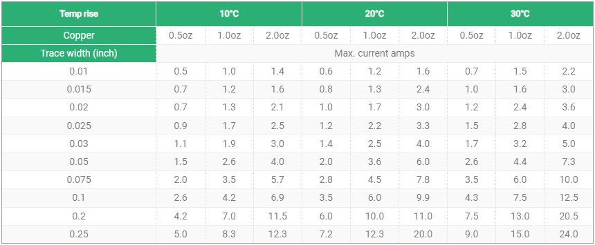
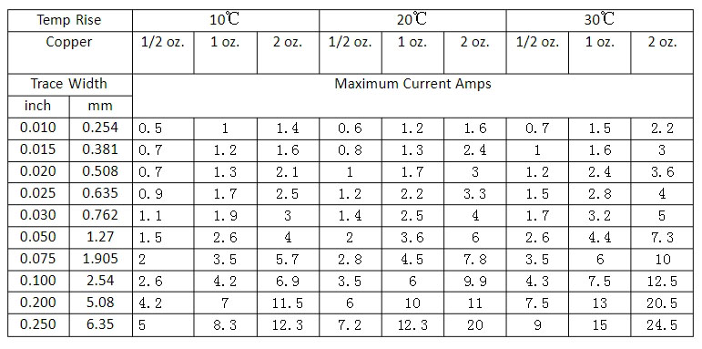
The relationship between the line width, copper thickness and current passing through the PCB board

1 foot = 12 inches
1 inch = 1000 mil
1mil = 25.4um
1mil = 1000uin mil is sometimes called inch
1um = 40uin (some companies call microinches “microinches”, which are actually microinches)
1OZ = 28.35 grams per square foot = 35 microns

The relationship between the line width, copper thickness and current passing through the PCB board

PCB copper thickness current comparison table

Copper foil width Copper foil thickness
70um 50um 35um
2.50mm 6.00A 5.10A 4.50A
2.00mm 5.10A 4.30A 4.00A
1.50mm 4.20A 3.50A 3.20A
1.20mm 3.60A 3.00A 2.70A
1.00mm 3.20A 2.60A 2.30A
0.80mm 2.80A 2.40A 2.00A
0.60mm 2.30A 1.90A 1.60A
0.50mm 2.00A 1.70A 1.35A
0.40mm 1.70A 1.35A 1.10A
0.30mm 1.30A 1.10A 0.80A
0.20mm 0.90A 0.70A 0.55A
0.15mm 0.70A 0.50A 0.20A

PCB copper thickness current comparison table

PCB copper content

The copper content of PCB copper foil is generally 90% and 88%.

Copper foil is made of copper and a certain proportion of other metals. There are two common specifications of copper foil, namely 90% and 88% copper content. The size of these two specifications of copper foil is 16*16cm, which is widely used in various occasions where copper foil is needed, including PCB manufacturing. In PCB manufacturing, copper foil is the basic material of the circuit board, and its thickness and copper content have an important influence on the electrical performance and durability of the circuit board. The thickness of copper foil is usually expressed in OZ (ounces). The standard PCB copper thickness range is 1/4OZ-6OZ. The specific thickness includes 1OZ, 2OZ, 3OZ, 4OZ, 5OZ, 6OZ, which correspond to different copper thickness sizes, such as 35um, 70um, 105um, 140um, 175um, 210um. In practical applications, the commonly used copper thicknesses are 1OZ, 2OZ, 3OZ, 4OZ, etc. These copper thicknesses can meet the needs of most electronic products.

The copper content of PCB copper foil is generally 90% and 88%.

Why is the copper foil on the surface of PCB copper+plating?

The copper foil on the surface of the PCB adopts the copper+plating method, mainly because this treatment method can provide better conductivity and protection circuit. ‌Copper foil is the conductor of PCB, and its basic material is copper, while plating (plating) is a layer of metal added on the basis of copper foil by electroplating or other methods, usually tin, gold or other alloys, to provide additional protection and enhance electrical performance. ‌The reasons and advantages of this treatment method are as follows: ‌

  1. Conductivity: Copper has good conductivity and is an ideal medium for the flow of electrons. ‌In PCB, copper foil is used as a conductive layer to connect various electronic components and ensure smooth transmission of current. ‌
  2. Protective circuit: By adding plating, such as tin or gold, to the copper foil, additional protection can be provided to prevent the copper foil from being oxidized or corroded, thereby protecting the long-term stability and reliability of the circuit board. ‌
  3. Enhanced electrical performance: Plating not only prevents copper foil from being oxidized, but also enhances electrical performance by selecting appropriate plating materials, such as using gold plating to improve the corrosion resistance and conductivity of the circuit board. ‌
  4. Cost considerations: Although gold is an expensive metal, the use of gold plating in certain key signal lines or high-density interconnection areas can significantly improve the performance and reliability of the circuit board, especially in reducing signal loss and interference in high-frequency signal transmission.

You may also like

Do you know the relationship between copper thickness and circuit width & spacing?
Saturday, September 2nd, 2023

We know the precision control and performance of a product are paramount, only know that PCB can be built with a nice function, so, to understand the intricate relationship between copper thickness and circuit width and spacing is pivotal. These two parameters are like the gears of a well-oiled machine, interlocking in ways that significantly influence the printed circuit board‘s functionality, signal integrity, and manufacturability. If the designer does not consider the relationship between these two, the design may need to be modified in subsequent production.

In order to avoiding this information, let’s embark on a deeper exploration of this dynamic relationship to uncover its nuances and implications now,

Frist of all, we need to know some basic information about PCB, like copper thickness, circuit width and spacing.

  1. The Essence of Copper Thickness

Copper, known for its exceptional electrical conductivity, is the lifeblood of any PCB. The copper thickness refers to the amount of copper deposited onto the board’s surface during fabrication. It’s the foundation upon which the traces, the intricate pathways that carry electrical signals, are built. The standard copper thickness is often measured in ounces per square foot (oz/ft²) or micrometers (µm). Common options include 1oz (35µm), 2oz (70µm), and even higher, it depends on customer’s requirement.

  • Circuit Width and Spacing

Circuit width and spacing, though often overlooked, are integral components that determine a PCB’s performance, integrity, and overall functionality. Circuit width refers to the dimension of the conductive traces, while spacing pertains to the distance between these traces. These seemingly simple dimensions have a profound impact on the PCB’s behavior.

Secondly, Unveiling the Intricate Relationship

The relationship between copper thickness, circuit width, and spacing is a sophisticated interplay of electrical properties, heat dissipation, and signal integrity. Let’s delve deeper into this complex web of interactions:

Current-Carrying Capacity and Copper Thickness: Copper thickness directly influences a trace’s ability to carry current without succumbing to overheating. Thicker copper translates to higher current-carrying capacity and reduced resistive losses. However, the trade-off is that wider traces are necessary to accommodate the increased copper thickness.

Resistance and Circuit Width: Wider traces exhibit lower resistance, which in turn reduces voltage drop and enhances the efficiency of signal transmission. Designers must strike a balance between trace width, copper thickness, and available board space.

Spacing and Unwanted Interactions: As circuit spacing decreases, the probability of unwanted interactions, such as crosstalk and electromagnetic interference, rises. Thicker copper can exacerbate these issues due to its larger cross-sectional area. Maintaining appropriate spacing between traces is pivotal to prevent signal degradation and maintain integrity.

Heat Dissipation and Trace Width: Thicker copper also aids in better heat dissipation, a crucial consideration for power-intensive applications. However, this can necessitate wider traces to manage the thermal load effectively.

Signal Integrity and Crosstalk: Smaller spacing reduces the risk of crosstalk, but it’s a double-edged sword. Thicker copper traces may introduce higher capacitance, altering impedance and potentially impacting signal integrity. This delicate balance requires careful consideration during design.

For now, we have known the relationship between them, how to develop a best design between the circuit width & spacing and copper thickness, which depends on what’s you really want, the huge current or heat management? Following details should be considered if you want to develop the best circuit width & spacing.

Current Requirements: Start by understanding the current requirements of your traces based on the components and operational conditions. Selecting the appropriate copper thickness and trace width ensures the PCB can handle the anticipated loads.

Thermal Management: Thicker copper facilitates heat dissipation, which is advantageous for power-dissipating components. However, remember that it might necessitate wider traces to ensure effective heat transfer.

Manufacturability: While thicker copper can enhance current-carrying capacity and heat dissipation, it might pose manufacturing challenges. Consult with PCB manufacturers to align your design choices with their capabilities.

Signal Integrity Analysis: Utilize simulation tools to analyze signal integrity, especially when dealing with smaller spacing and thicker copper. These tools provide insights into impedance matching, potential crosstalk, and overall performance.

Flexibility VS Rigidity: While thicker copper enhances many aspects, it can impact the PCB’s flexibility, crucial for certain applications. Evaluate the mechanical demands of your project and strike the right balance.

Regarding metal core PCB in Best Technology, the copper thickness and its accordingly circuit width & spacing like below, furthermore, it would be better if you can let me know your copper thickness before checking your drawing, we will give you the best solution before formal production.

Copper thicknessMinimum circuit widthMinimum circuit spacing
0.5-2oz0.25mm0.23mm
3oz0.35mm0.3mm
4oz0.4mm0.38mm
(trace_design_guide_of_MCPCB)

Conclusion: Striking the Optimal Balance

The intricate relationship between copper thickness, circuit width, and spacing in PCB design embodies a delicate equilibrium that significantly influences a design’s performance and functionality. This nuanced interplay directly impacts parameters such as current-carrying capacity, resistance, heat dissipation, and signal integrity.

Achieving the optimal balance between these factors requires a deep understanding of electrical properties, thermal considerations, and signal behavior. Designers must carefully evaluate the specific requirements of their projects and leverage simulation tools to fine-tune their choices. Collaboration with PCB manufacturers ensures alignment with manufacturing capabilities.

The dynamic nature of this relationship underscores the constant evolution of PCB technology. As devices become smaller, faster, and more interconnected, the demand for intricate layouts intensifies. Designers must continuously adapt to new challenges, pushing the boundaries of what’s achievable while adhering to the fundamental principles that govern PCB design.

You may also like

How to choose the thickness of copper on PCB
Tuesday, March 24th, 2020

As a general rule, this thickness of copper foil for single-sided PCB and double-sided PCB is approx.35um(1.4mil). There is also another specification, which is 50um and 70um. The surface thickness of multilayers PCB is 35um(1oz(1.4mil)) generally, and the inner layer has a thickness of 17.5um(0.7mil). 70% of PCB uses the copper foil thickness of 35um. This is based on PCB purpose and signal voltage as well as current. In addition, for PCB requiring large current, copper thickness of 70um or 105um will be used, and 140um is also used in some cases.

heavy copper pcb
heavy copper pcb

People often use OZ to represent copper thickness. 1OZ stands for the thickness of 1OZ copper covered on the area of 1 square feet evenly. I.e. approx. 1.4mil. The weight of unit area is used for representing the average thickness of copper foil. I.e. 1oz=28.35g/ FT2(FT2 stands for square feet, 1 square feet=0.09290304 square meter).

For heavy copper PCB, if the substrate has a thickness of 1 to 3mm, then the thickness of composite copper foil will be approx.35um. If the substrate has a thickness of less than 1mm, then the thickness of composite copper foil will be 18um. If the substrate has a thickness of above 5mm, then the thickness of composite copper foil will be 55um.

heavy copper pcb
heavy copper pcb

The thickness of copper foil(wiring width) will influence current. Even though there is a formula to directly calculate the largest current loading capability of copper foil, things will get more complex when designing wiring. In this case, safety should be fully taken into consideration during design.

Copper foil will have different thickness, if there are different purposes. General 0.5OZ, 1OZ and 2OZ copper foil are most widely used for consumption and communication products. The thickness of copper foil above 3OZ belongs to heavy copper products, which are widely used for products with large current, such as high pressure products, and power supply board.                                               

This is all about how to choose proper copper thickness during your project. Hope this is helpful to you. If you are still confused, please contact Best Technology. We have online customer services for 24 hours.

You may also like