If you’ve ever made a pie with your kids, you know that the thickness of your crust is important. Too thin, and the pie falls apart into a mess of filling. Too thick, and you might as well be chewing on a loaf of bread. Getting the thickness just right is what makes a pie worth eating.
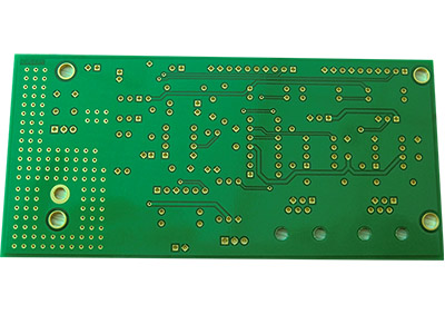
Even though PCB substrate materials are non-conductive and do not carry current, the board material still affects the electrical performance. FR4 PCB substrate is widely used, and a thorough understanding of this material is very necessary.
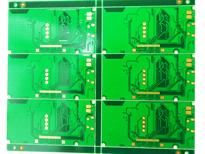
FR4 Thickness Design Considerations
If you start your design process by choosing the correct board thickness, you will avoid to redesign later. A number of factors are influenced by the board thickness. Before you start designing your board, think about the following design issues:
Form factor and flexibility: Does your PCB have a strict form factor requirement? Thinner boards tend to be used in smaller devices and can flex more than a thicker board. A more flexible board may be unusable with a pick & place machine. Electrical connections in flexible boards can also break unless they have some mechanical support.
Components and connections: Will the device have any components that require the Printed Circuit Board to have a specific thickness? Components like USB edge connectors and some through-hole components require PCB in correct thickness. BGA connectors generally require thicker boards.
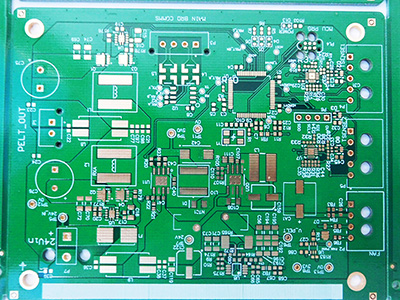
Impedance matching: Traces on adjacent layers in multi-layer boards form a capacitor, and the layer thickness and its dielectric constant determines the equivalent capacitance. Impedance matching is critical, and the capacitance must be taken into consideration when designing the board. This is especially true in HDI PCB.
High-speed devices: If you are working with a high-speed device, FR4 is always not the best option, and some other material should be used instead. FR4 PCB could be used in high-speed devices when the layers are coated with high-speed laminates. These laminates offer significantly improved electrical performance over standard FR4, and generally a combination of FR4 and a high-speed laminate may be preferable to an alternative material.
RF losses: FR4 tends to have higher losses than other PCB materials that are specialized for RF applications. Traces on FR4 will have larger attenuation at RF frequencies than other specialized materials for a given board thickness. The board thickness also changes the effective dielectric constant of the board, which then changes the required impedance matching in RF circuits.
Thermal and Reliability Considerations
All materials expand at higher temperatures, and the thermal expansion coefficient must be taken into consideration when choosing the board thickness. The thermal expansion coefficient of FR4 changes drastically above the material’s glass transition temperature (140℃). The board can become electrically and mechanically unstable when the board operates above the glass transition temperature.
The reliability of the trace materials, laminate materials, and solder joints on a PCB laminate are determined by the resistance to thermal cycling. When the thermal expansion coefficients of the different materials are mismatched, fatigue occurs after repeated thermal cycling. Copper plating in vias and solder balls are especially vulnerable to damage under thermal cycling.
This is a greater problem in thick FR4 PCB with high aspect ratio vias. Plating damage in through-hole vias, lifted pads, and cracked surface resin can occur under the stress caused by thermal cycling. A thicker board will have a larger expansion magnitude for a given via aspect ratio, resulting in more damage to the board and the electronic components. Thermal stresses can be huge when an FR4 PCB runs above the glass transition temperature.
Volumetric expansion is also critical in rigid-flex FR4 PCB. Thermoplastic adhesives with low glass transition temperatures and high Z-direction expansion coefficients can exhibit very large volume expansion at high temperature. Z-direction expansion in these situations can be as large as 500 ppm/ƒ.
Even though a thicker FR4 PCB has greater thermal mass and can dissipate more heat from electronic components, there is also the potential for more damage due to thermal expansion. Therefore, how to choose between a thick and thin FR4 PCB that satisfies all other requirements, the thinner board may be a better choice if the FR4 PCB will undergo thermal cycling frequently.
If you have any comments. queries or suggestions on this, welcome to contact us.


