GND Full Form
GND stands for “Ground.” It is one of the most fundamental elements in any electrical or electronic system. It provides a common return path for electric current, ensuring the stability and safety of a circuit.
What is the GND of a Circuit?
In a circuit, GND serves as a reference point for voltages within the system. It is typically where the voltage level is zero, enabling the safe and reliable return of current. Connecting components to GND helps establish a common potential, which ensures the proper flow of current. Without it, the circuit would not have a defined voltage reference, leading to erratic behavior.

Types of Grounding
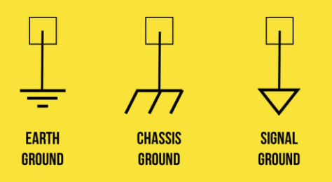
Chassis Ground: Used for safety, this type of grounding connects the circuit to the physical frame or body of the device. It protects users and components by directing fault current to the device’s casing and then safely to the Earth if necessary. This type of ground is common in devices that handle higher currents or voltages.
Signal Ground: Signal grounding is essential in circuits where communication and precision are vital, such as in data transmission and low-power applications. It provides a stable reference for different signal levels, minimizing noise that can disrupt performance.
Earth Ground: This type of ground connects directly to the Earth, providing an essential layer of safety. In situations where high power levels are present, Earth ground dissipates excess current safely into the soil, preventing damage and protecting against electric shock.
Importance of GND in Circuits
GND does more than just connect parts of a circuit; it plays a foundational role in circuit performance and safety.
- Personal safety
Ground grounding is one of the important measures to ensure circuit safety. By connecting the live metal part of the circuit to the ground, the ground wire can quickly direct the charge of the metal part to the ground, reducing the risk of electric shock. Especially in the electrical equipment in the metal shell and wire may be charged for various reasons, if there is no grounding wire protection, people contact these live metal parts will have the risk of electric shock.
- Protective electrical equipment
The grounding wire can effectively protect the equipment, avoid conducting overvoltage, and ensure the normal operation and long-term use of the equipment. The ground cable can direct the excess current or potential in the device to the ground, preventing electrical leakage, and avoiding equipment damage and fire.
- Lightning protection
The ground cable plays an important role in lightning protection. By introducing the lightning current generated by lightning into the ground, the ground cable can effectively prevent lightning damage to the power or electronic equipment and prolong the service life of the equipment.
- Ensures normal operation of the equipment
In some equipment that requires electricity, the ground cable can ensure that the equipment can still operate normally in case of power failure. The ground wire can conduct the current to the ground to ensure that the small load potential is still normal.
- Electromagnetic compatibility
In electronic equipment, the ground wire can also reduce the mutual interference between signals to ensure the stability and reliability of the system. With the complexity of electronic equipment and the increase of signal frequency, electromagnetic compatibility in grounding design must be paid special attention.
How GND is Used in Circuits?
The use of GND in circuits varies depending on the design requirements:
Single-Point Grounding: In this method, all ground connections meet at a single point. This setup is effective for small circuits, as it prevents ground loops—an issue where multiple paths create unwanted current flow that generates noise.
Multi-Point Grounding: In larger or high-frequency circuits, multi-point grounding may be used. It allows for ground connections at various points, helping to manage large currents or rapid changes in current. However, this setup requires careful planning to avoid loops that could disrupt the circuit.
Ground Planes: Ground planes are continuous areas of copper on a PCB connected to GND. They provide a low-impedance path for current, which reduces noise and stabilizes the circuit. Ground planes are essential for high-speed and RF circuits, where noise management is critical.
How Do You Find the Ground of a Circuit?
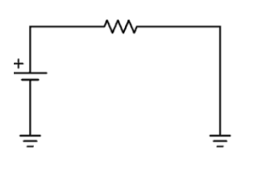
Finding the ground point in a circuit involves identifying the section connected to the zero-voltage reference. In circuit diagrams, GND is represented by a specific symbol—usually a line or triangle pointing down. Physically, it is marked on PCBs or found on specific pins of connectors or components.
To confirm a ground connection:
Use a Multimeter: Set it to voltage mode and place the black probe on the suspected GND point. Place the red probe on other parts of the circuit. If you get a zero-voltage reading between the probes, the black probe is on the GND.
How to Design the GNDs of a Circuit?
Designing the GNDs in a circuit is a careful process. Here are some guidelines:
- Plan Your Layout: Start by mapping out the circuit layout to visualize the flow of current. Position the components in a way that promotes efficient current flow to the GND.
- Use Ground Planes: In PCB design, ground planes provide continuous paths that help stabilize current flow and minimize resistance. This approach reduces electrical noise and enhances circuit performance.
- Separate Grounds for Specific Functions: For mixed-signal circuits, separate analog and digital grounds are important to prevent signal interference. Connecting them at a single point helps manage potential issues without creating loops.
- Minimize Loop Areas: Reducing the size of current loops lowers electromagnetic interference (EMI), which can affect nearby components and circuits.
- Connect Ground Points Properly: Use wide traces or planes to connect GND points, as narrow traces can increase impedance and cause voltage drops.
Is GND Positive or Negative?
In most circuit designs, GND is considered the negative point, providing the return path for current. However, there are exceptions, such as specific power supply configurations where GND might be the positive reference. This depends on the system’s design, so always check the schematic.
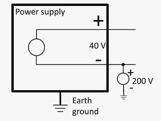
What Will Happen if No Ground GND is Connected to the Circuit?
A circuit without a GND will face significant issues:
1. Unstable Operation: Without a ground, components lack a voltage reference, leading to unpredictable and unreliable performance.
2. Noise Susceptibility: Circuits without GND are more prone to interference, which can distort signals and impair function.
3. Safety Hazards: Ungrounded circuits can pose a shock risk. If current has no path to return safely, it could end up flowing through unexpected routes, potentially damaging components or causing harm.
Designing the GNDs of a circuit is as crucial as choosing the right components. A well-thought-out ground layout can make a significant difference in circuit stability, noise reduction, and overall performance. By understanding the types of grounding and incorporating them effectively, you create circuits that not only work but do so reliably and safely. Always prioritize proper GND design to ensure long-lasting, efficient circuit operation.


