

On a schematic diagram, letters and numbers serve as an organized and systematic way to represent the various components, their relationships, and the specifics of the PCB circuit design. Here’s an extended explanation of the key elements represented by these symbols.
Component designators
Component designators are typically a letter or combination of letters that denote the type of electrical or electronic component. These letters are standardized, so engineers and technicians across the world can easily understand the schematic.
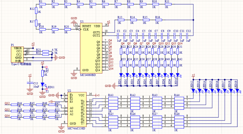
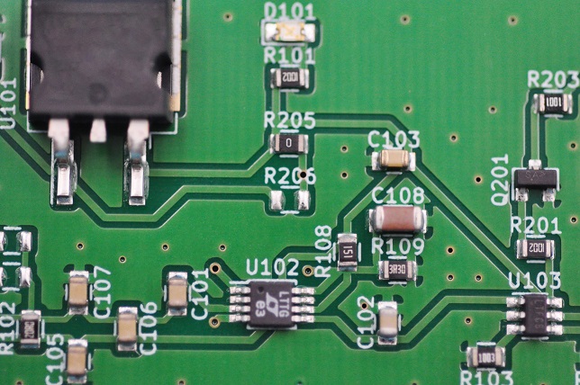
- R: Resistor (e.g., R1, R2) – Indicates a resistor, with numbers differentiating multiple resistors in the circuit.
- C: Capacitor (e.g., C1, C2) – Refers to capacitors, either for storing charge or filtering signals.
- L: Inductor (e.g., L1, L2) – Shows inductors, which store energy in a magnetic field.
- D: Diode (e.g., D1, D2) – Marks diodes, which allow current to flow in one direction.
- Q: Transistor (e.g., Q1, Q2) – Represents a transistor, which can be used for switching or amplification.
- U: Integrated Circuit (IC) (e.g., U1, U2) – Denotes an IC, a collection of components like transistors, diodes, and resistors in one package.
- J: Connector (e.g., J1, J2) – Represents a connector or jack where an external connection can be made.
- SW: Switch (e.g., SW1, SW2) – Indicates a switch that can open or close the circuit.
- TP: Test Point (e.g., TP1, TP2) – Refers to a point in the circuit where voltage or signal measurements can be taken.
- LED: Light Emitting Diode (e.g., LED1, LED2) – Represents an LED, a special type of diode that emits light.
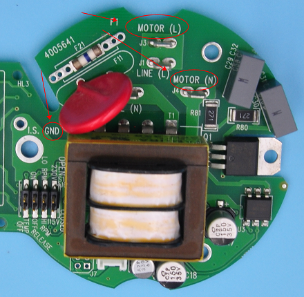
- F: Fuse (e.g., F1, F2) – Denotes a fuse, a protective device to prevent overcurrent.
- VR or P: Variable Resistor/Potentiometer – A resistor whose resistance can be adjusted, often used for tuning circuits.
- M: Motor (e.g., M1, M2) – Marks a motor, converting electrical energy into mechanical motion.
Above just few common letters used in PCB schematics, here we summarized a chart for your better reading.
| Letter | Represents Components |
| D | Diode/Inverter (sometimes inverter use it) |
| Q | Transistor (also used instead of V and VT) |
| C | Capacitor |
| L | Inductor |
| R | Resistor |
| K | Relay |
| T | Transformer |
| X、Y | Crystal Oscillator |
| U、IC | Integrated Circuit |
| M | Motor |
| CX | High Voltage Ceramic Capacitor |
| CY | High Voltage Thin Film Capacitor |
| CE | Electrolytic Capacitor |
| VR | Variable Resistor |
| RT | Thermal Resistor |
| RP | Potentiometer |
| RG | GND |
| J | Joggle |
| JP | Jumper |
| FU | Fuse |
| N | Optocoupler |
| B、BZ | Buzzer |
| SCR | Unidirectional Thyristor |
| TRIAC | Bidirectional Thyristor |
| FB | Ferrite Bead |
| ZD | Zener Diode |
| LED | Light-Emitting Diode |
| SPK | Speaker |
| S、SW | Switch |
| DB | Bridge Diode |
| TP | Test Point |
Reference Numbers
Reference numbers provide a clear and organized way to distinguish between multiple instances of the same type of component within a schematic. Without these numbers, it would be difficult to identify and refer to specific components during assembly, troubleshooting, or modifications.
For example:
- R1, R2, R3: These are three different resistors in the same circuit.
- C1, C2, C3: Refers to different capacitors.
The numbers ensure there’s no confusion when discussing the schematic, ordering parts, or identifying where a fault might lie in the circuit.
Sometimes, designer use [Component Designator] + [Number] structure: the component designator is a letter or combination of letters (e.g., R for resistor, C for capacitor, U for IC).
Or the number is a sequential identifier, starting from 1 and incrementing for each new component of that type (e.g., R1, R2, R3 for three resistors).
Values and Ratings
Numbers are often placed near components to indicate their electrical values. These values help in understanding the component specifications and performance:
Resistors: The value of resistance is given in ohms (Ω). For example, “R1 100Ω” indicates that resistor R1 has a resistance of 100 ohms.
Capacitors: The capacitance is usually specified in farads (often microfarads or picofarads). For example, “C1 10μF” refers to a capacitor with a capacitance of 10 microfarads.
Inductors: The inductance is given in henries (H). For example, “L1 100mH” means the inductor has a value of 100 millihenries.
Voltage Ratings: Components may have voltage ratings marked on them, indicating the maximum voltage they can handle safely. For example, a capacitor might have “50V” written next to it, meaning it can withstand up to 50 volts.
Tolerance and Power Ratings: Some components may include additional ratings like tolerance (e.g., ±5%) for resistors or power ratings in watts (e.g., 0.25W for resistors).
Pin Numbers and Labels
Components like ICs, connectors, and transistors may have multiple terminals or pins. On the schematic, pin numbers are often labeled to indicate where each connection needs to be made. For example, an IC might have pin numbers 1, 2, 3, etc., and the schematic helps you see how these pins connect to other parts of the circuit.
For connectors and ICs, pin labels like VCC, GND, Output, or specific functions (e.g., Reset, Clock) may be used to denote what each pin does. In a slide potentiometer, for instance, the pinout might be labeled as Output, VCC, and GND to clarify the connection points.
Nodes and Signal Labels
Nodes: In a schematic, a “node” refers to a junction where different components are connected. Nodes might be labeled with numbers or names to represent different parts of the circuit.
For instance, all components connected to ground might have the label GND.
Similarly, all components connected to a 5V supply might have the label VCC or +5V.
If a schematic involves multiple pages or complex designs, signals may be labeled with text to show where a wire is going or what function it performs (e.g., CLK for clock signal, DATA for data line).
Wire and Trace Identifications
Wires and traces in schematics are shown as lines connecting the components. These lines show the paths through which electrical signals and currents flow. Sometimes, wires are labeled with names or numbers, especially if the schematic is very complex or spans multiple sheets. For example: wires may be labeled with names like SCL, SDA (for I2C communications), or simply A1, A2 to denote different connections.
Voltage and Current Values
Some schematics include voltage or current values directly on the diagram to show how much voltage should be present at specific points or how much current is flowing through a component. For instance: 5V or 12V might be written near a power supply line, indicating the expected voltage at that point in the circuit.
Current values may be given in milliamps (e.g., 20mA), showing the expected current flowing through a component like an LED.
Special Symbols
Schematics may also include symbols to indicate specific characteristics or features of the circuit, such as:
- Ground (GND): The symbol for ground shows where components are connected to a common reference point (usually zero volts).
- Power Rails: Symbols like +5V or +12V indicate where power is supplied in the circuit.
- Oscillators or Clock Signals: These can be shown with special symbols or labels, such as a waveform or the abbreviation CLK.
There is needed to be noted that, the meaning of the letters/numbers on the PCB board did not form a strict standard, is not always consistent with the above table or above mentioned, they are just for easy to communicate and manufacture. If special labels existing your customer’s schematic, please communicate with your client.