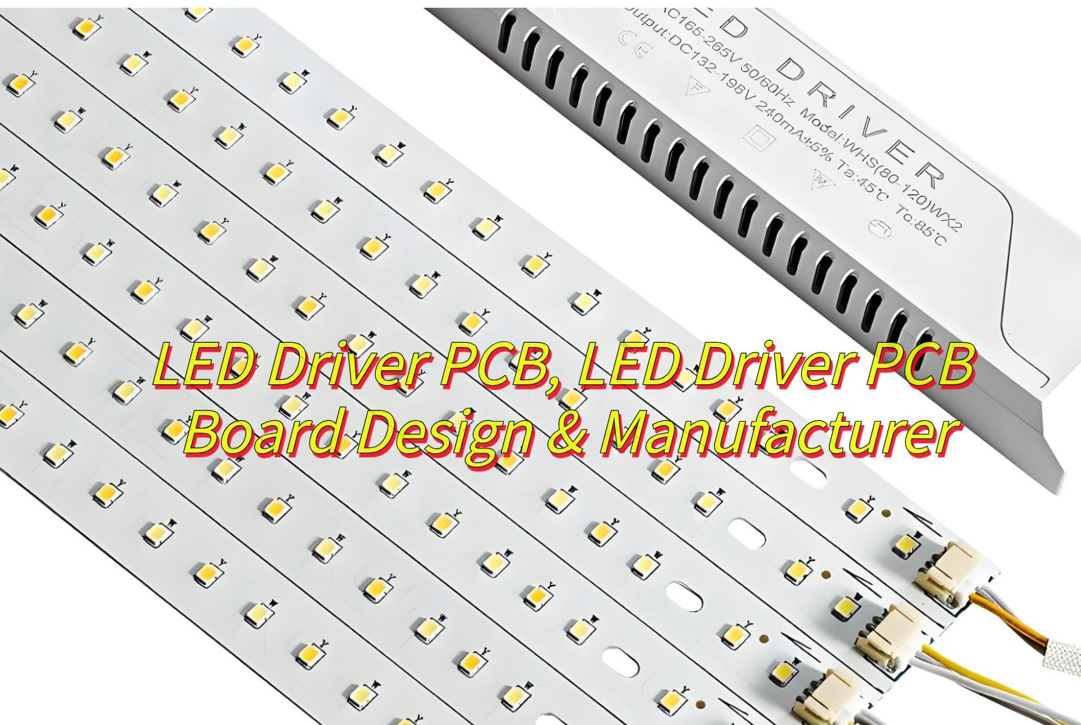
Are you looking for a LED Driver PCB manufacturer with design service? Let’s explore more about how to design LED driver PCB and how to select a reliable LED driver PCB manufacturer.
At Best Technology, we focus on LED driver PCB manufacturing and designing over 18 years. We prioritize IP Protection & NDAs, ensuring your designs are safeguarded through strict confidentiality agreements and secure data handling. And we maintain Quality & Compliance with certifications like ISO 9001, UL, and CE, guaranteeing adherence to the highest industry standards and safety regulations. Then we can provide 48 hours rapid prototyping service because we have stable electronic supply chain. If you have any request for LED driver PCB board, please feel free to contact us: sales@bestpcbs.com
What Is LED Driver PCB?
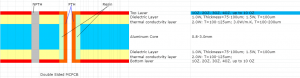
An LED driver PCB is a printed circuit board specifically designed to control and regulate the power supplied to LEDs. It converts incoming electrical power (e.g., AC mains or DC sources) into the precise voltage and current required by the LEDs, ensuring stable operation, brightness consistency, and protection against voltage fluctuations or overheating. Key components on the board include voltage regulators, current controllers, and thermal management elements like heat sinks. LED driver PCBs are critical in applications like residential/commercial lighting, automotive headlights, and digital displays, as they optimize energy efficiency, extend LED lifespan, and enable features like dimming or color control.
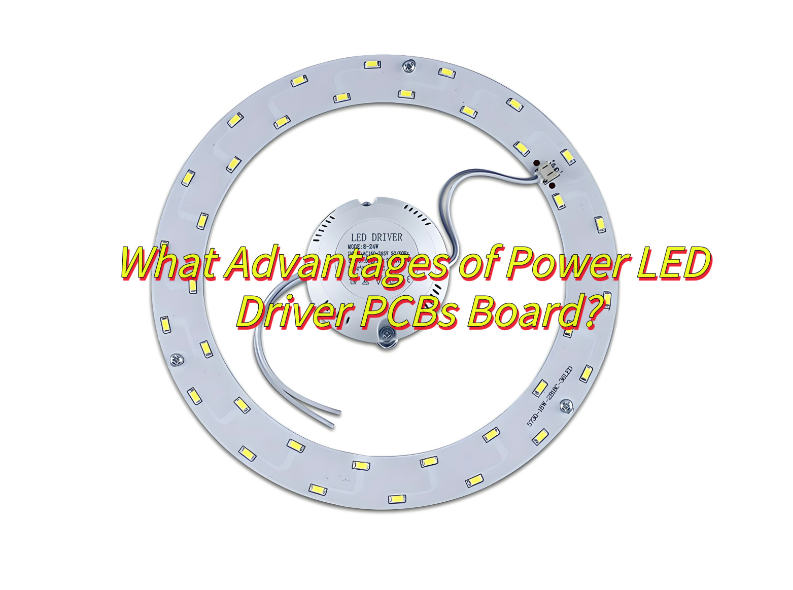
What Advantages of Power LED Driver PCBs Board?
Here are five main advantages of a Power LED Driver PCB:
- High Efficiency and Energy Saving-Optimized power topologies (e.g., Buck, Boost, LLC resonant circuits) deliver efficiency up to 90%+, minimizing energy waste.
- Stable Current Regulation-Advanced control algorithms maintain precise LED current across wide input voltage ranges (e.g., 90–264Vac), ensuring consistent illumination.
- Compact and Integrated Design-High-density component placement and SMD technology reduce PCB size, enabling sleek, space-efficient lighting solutions.
- Robust Thermal Management-Multi-layer PCBs with thermal vias and copper heat sinks efficiently dissipate heat, enhancing reliability in high-temperature environments.
- Electromagnetic Compatibility (EMC)-Compliance with international EMC standards (e.g., IEC/EN 55015) minimizes electromagnetic interference, ensuring seamless integration into smart systems.
How to Design a 100W LED Driver PCBs Board?
Here’s a 100W LED driver PCB board design process:
1.Circuit Design & Schematic (LED Driver PCB Schematic)
- Begin with a topology like Flyback or LLC resonant. Use design tools (e.g., Altium, Eagle) to create a schematic, ensuring components (MOSFETs, capacitors, inductors) are rated for 100W.
2.Component Selection
- Choose high-efficiency MOSFETs, capacitors (e.g., electrolytic, ceramic), and inductors. Verify their current, voltage, and thermal ratings for 100W operation.
3.Thermal Management
- Integrate heat sinks, thermal pads, and vias into the PCB layout to efficiently dissipate heat from power components.
4.PCB Layout & LED Driver PCB Schematic
- Place power components close together to minimize high-current trace lengths.
- Use wide traces (e.g., 2–3mm) for power delivery to avoid voltage drop.
- Separate power, ground, and control signals in a multilayer stack-up.
5.EMI/EMC Compliance
- Add input/output filters, shielding, and proper grounding to meet EMI/EMC standards (e.g., CISPR 32, FCC Part 15).
6.Prototyping & Testing
- Fabricate a prototype based on the LED driver PCB schematic and test for efficiency, thermal performance, and EMI compliance.
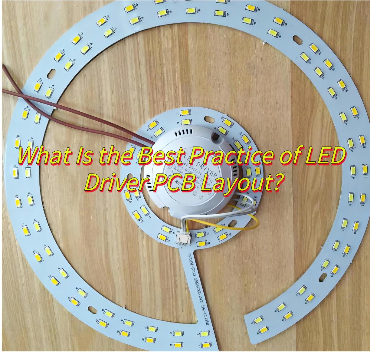
What Is the Best Practice of LED Driver PCB Layout?
Here’s a streamlined guide to LED driver PCB layout best practices:
- Component Placement
Cluster power transistors, capacitors, and inductors to shorten high-current traces and minimize inductance. - Thermal Management
Locate heat-sensitive components (e.g., MOSFETs, ICs) near cooling solutions. Use thermal vias to efficiently conduct heat away. - Ground Plane Design
Maintain a solid, unbroken ground plane to reduce EMI and ensure clean signal returns. - Trace Width Sizing
Calculate trace widths based on current load (e.g., 1mm per 1A) to prevent voltage drop and overheating. - Layer Stack-up
Isolate power, ground, and signal layers in multilayer boards to minimize cross-talk and noise.
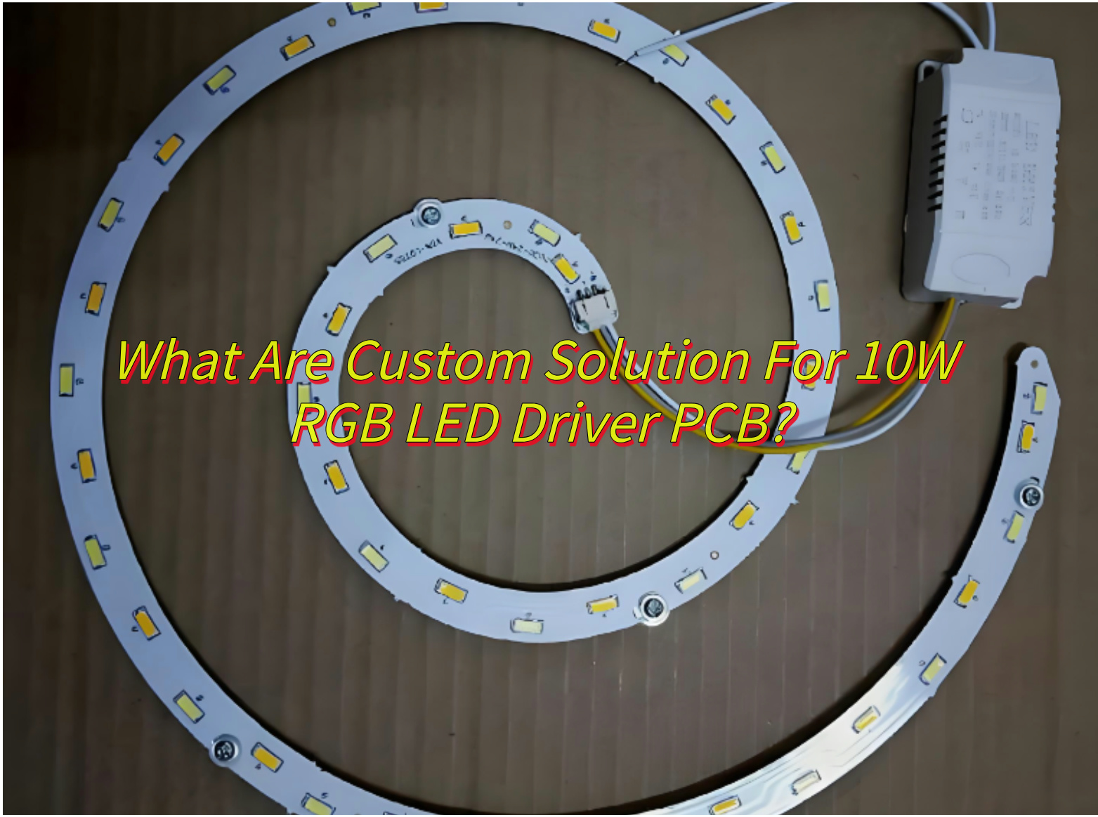
What Are Custom Solution For 10W RGB LED Driver PCB?
Here’s a concise guide to custom solutions for a 10W RGB LED driver PCB:
- Color Control Interface
Implement PWM or analog control for precise RGB color mixing and dynamic lighting effects. - Current Regulation
Use constant-current drivers for each RGB channel to maintain color accuracy and LED lifespan. - Dimming Compatibility
Design for compatibility with PWM, TRIAC, or 0-10V dimming systems to suit diverse applications. - Compact Design
Optimize PCB layout for a small form factor, using SMD components and efficient thermal management. - Protection Features
Include over-current, over-temperature, and short-circuit protection to enhance reliability.
How Is A Round LED Driver PCB Manufactured?
The production of round LED driver PCBs follows a specialized workflow to accommodate their unique geometry while maintaining electrical integrity. Below is the streamlined manufacturing process:
- Copper Clad Laminate Cleaning: Clean circular substrates (e.g., FR-4) to remove contaminants like dust or oxidation, ensuring adhesion for subsequent processes.
- Dry Film Lamination: Apply photosensitive dry film to the copper layer, followed by UV exposure through a circular mask to define the circuit layout.
- Development & Etching: Remove unexposed dry film using alkaline solutions; Etch away unprotected copper with ferric chloride or ammonium persulfate, forming conductive traces.
- Alignment & Pressing: Align multiple circuit layers (for multi-layer designs) using alignment holes, then bond them under high temperature and pressure with prepreg resin.
- Mechanical Drilling: Use CNC machines to drill holes for vias and component mounting, maintaining precision to avoid radial deviations.
- Electroless Copper Deposition: Deposit a thin copper layer on hole walls to establish electrical connectivity between layers.
- Outer Layer Shaping: Cut the PCB into a circular shape using CNC routers with diamond-coated bits. Fixtures ensure centering accuracy and smooth edges.
- Solder Mask: Spray or screen-print epoxy-based solder mask, leaving exposed pads for soldering.
- Surface Treatment: Apply HASL (Hot Air Solder Leveling) or ENIG (Electroless Nickel Immersion Gold) to prevent oxidation and enhance solderability.
- Testing: Automated Optical Inspection (AOI): Scan for defects like open/short circuits using high-resolution cameras.
- Silkscreen Printing: Add component labels or logos using UV-curable ink.
- Packaging: Seal in anti-static bags with desiccants to prevent moisture damage during transit.
How to Choose A Reliable LED Driver PCB Board Manufacturer?
Here are some ways to select a reliable LED driver PCB board manufacturer:
- IP Protection & NDAs-Partner with manufacturers who prioritize intellectual property protection by signing NDAs and implementing secure design safeguarding measures.
- Rapid Production Cycles-Prioritize manufacturers with streamlined processes for quick prototyping and fast production turnaround times to meet urgent deadlines.
- Quality & Compliance-Choose manufacturers holding certifications like ISO 9001, UL, or CE, ensuring adherence to quality standards and safety regulations.
- Design Expertise-Select a manufacturer with proven experience in LED driver PCB design, including efficient thermal management, EMI compliance, and optimized layouts.
- Premium Materials & Components-Ensure they use high-quality, application-specific materials and components to guarantee performance and longevity.
How to DIY 8W LED Driver PCB?
Here’s a simplified guide to DIY an 8W LED driver PCB:
- Design the Circuit
Use software like EasyEDA or KiCad to design your 8W LED driver circuit, ensuring proper component selection and layout. - Choose Components
Select an appropriate LED, driver IC, resistors, capacitors, and a power supply rated for 8W output. - Create PCB Layout
Design the PCB layout with component placement and trace routing optimized for your circuit. - Manufacture the PCB
Order the PCB from a fabricator or etch it yourself using a photoresist and etching solution. - Assemble Components
Solder all components onto the PCB, following the circuit diagram. - Test the Driver
Power up the PCB and test its functionality, ensuring it delivers the correct voltage and current to your LED.
In conclusion, that’s all about LED driver PCB board designing and manufacturing. if you have any issues with LED driver PCB board, please leave a message below this blog.