pcb
Home > Blog

Posts Tagged ‘MCPCB’

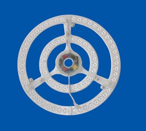
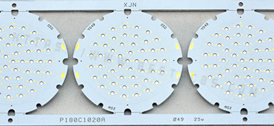
What Is led ring light pcb
Friday, August 2nd, 2024

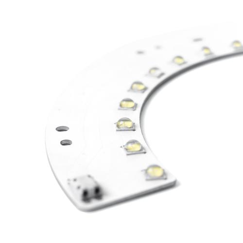
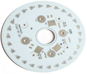
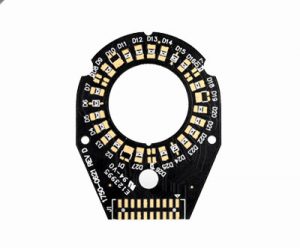
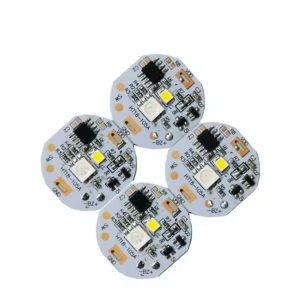
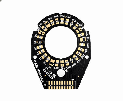
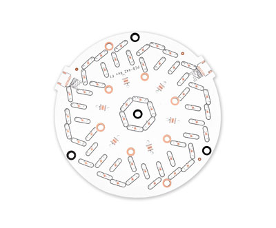
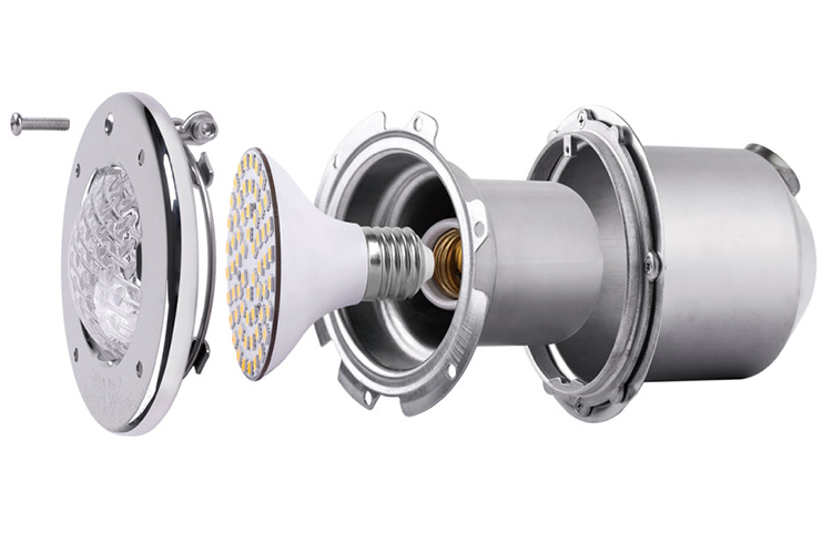
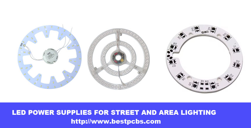
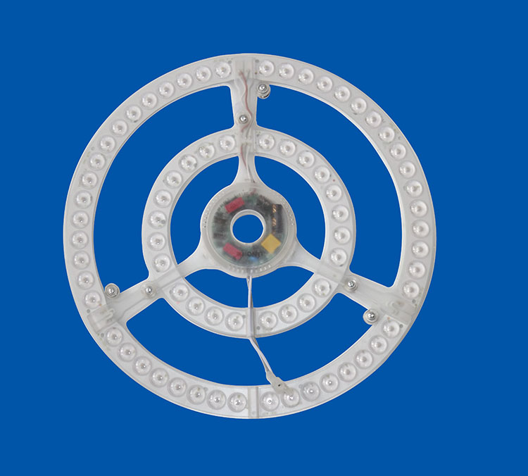
led ring light pcb leads the development of lighting industry with its innovative design, high efficiency and flexibility, bringing more intelligent and comfortable lighting experience to our life.

It is not only an integrated platform of electronic components, but also a perfect combination of modern technology and aesthetics, and is the focus of future lighting trends.

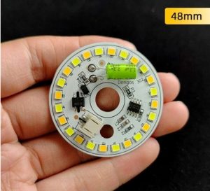
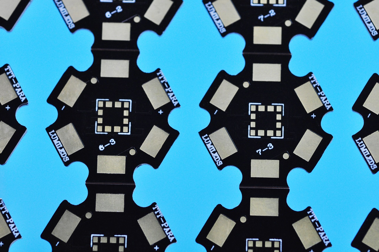
led ring light pcb, like a magic wand on the electronic stage, uses precise SMT technology to lightly attach LED components to it. Whether it is a warm small lamp for home decoration, efficient lighting in commercial space, or smart display inside the car, it is indispensable.

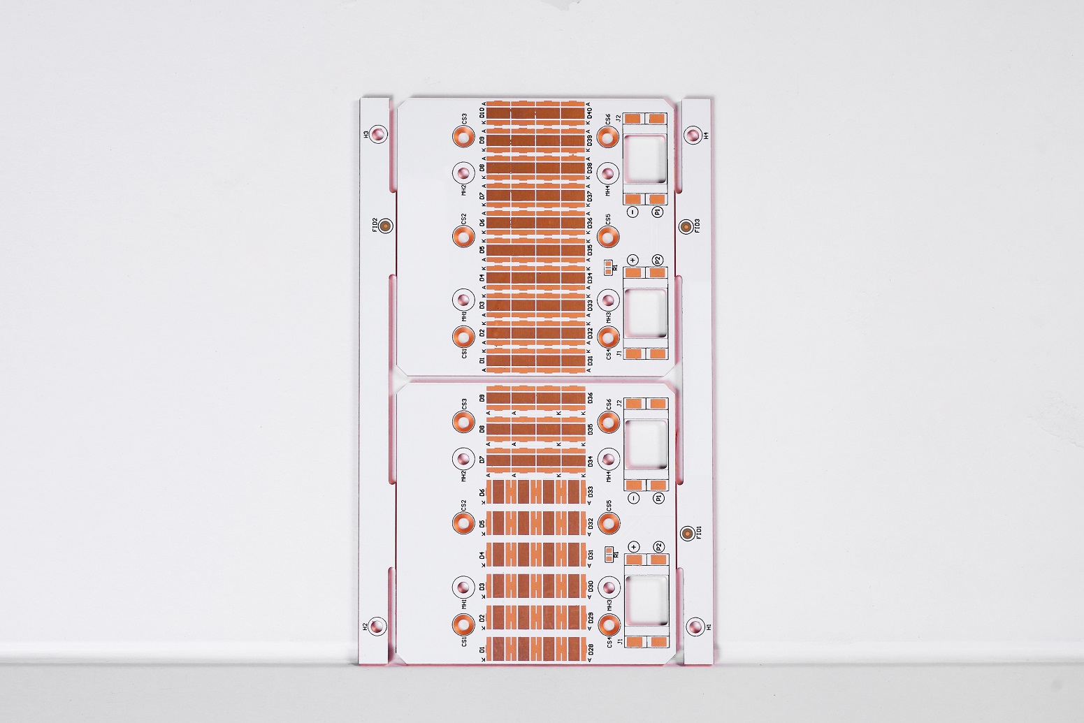
Its core structure includes efficient LED lamp beads, power cords that provide electricity, and intelligent controllers that adjust light effects, which together build an excellent lighting solution.

What Is led ring light pcb

Why use mcpcb for led ring light pcb

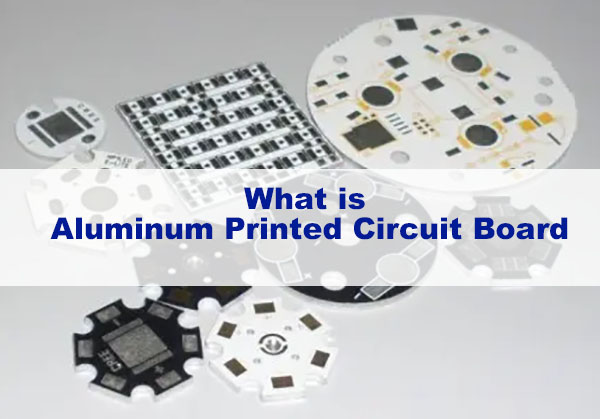
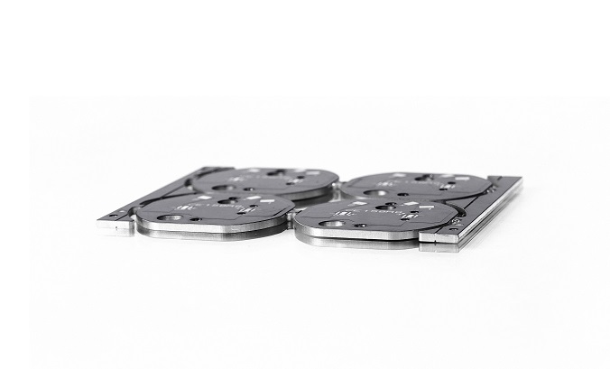
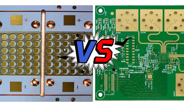
With the continuous development of LED technology, the heat generated by LEDs has gradually increased. The traditional FR4 printed circuit board (PCB) has been unable to meet the heat dissipation requirements due to its low thermal conductivity (only 0.36W/m.K). In order to solve this problem, the metal core printed circuit board (MCPCB) was proposed. It attaches the original printed circuit board to a metal with better thermal conductivity (such as aluminum and copper) to enhance the heat dissipation effect. The thermal conductivity efficiency of MCPCB is higher than that of traditional FR4 PCB, reaching 1W/m.K to 2.2W/m.K, which effectively improves the heat dissipation performance of LED PCB.

In addition, the use of MCPCB can also reduce the number of LEDs required to generate lighting, making it an ideal choice for street lights, automotive LED applications, and backlight unit applications. The use of metal substrates has practical advantages in heat dissipation, thermal conductivity, reliability, and electrical insulation, especially in harsh environments, and can also achieve reliable operation of LEDs. For example, using a metal substrate can reduce the LED junction temperature by 20-30°C, improve light output and enhance the overall performance of the product, ensure consistent UV light generation, and expand the possibilities of UV applications in various industries.
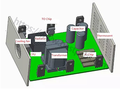
Unveiling the Components of LED PCBs

  • LED Chips: The heart of the LED PCB, these semiconductor chips emit light when current passes through them.
  • Substrate Material: The base layer of the PCB provides mechanical support and thermal conductivity.
  • Copper Traces: These conductive pathways connect the LEDs and other components, allowing current to flow through the circuit.
  • Solder Mask: A protective layer that covers the copper traces, safeguarding them from external factors and preventing short circuits.
  • Silkscreen: This layer contains markings and labels, providing important information about the PCB’s components and assembly.

Advantages of led ring light pcb?

Thermal performance advantages of metal substrate PCB

High thermal conductivity:
The thermal conductivity of metal substrate PCB is much better than that of traditional plastic substrates such as FR4. It can effectively conduct the heat generated by components, reduce the operating temperature of components, and improve the reliability and life of circuit boards.

Good thermal stability:
Metal substrate PCB can maintain good dimensional stability and electrical performance in high temperature environment, and is suitable for high temperature working environment.

Mechanical performance advantages of metal substrate PCB

High strength: Metal substrate PCB has high mechanical strength and rigidity, is not easy to deform and break, and can withstand large external forces and vibrations.

Good processability: Metal substrate PCB can be processed by conventional mechanical processing methods such as drilling and cutting, which is convenient for the production of circuit boards with complex shapes and sizes.

Electrical performance advantages of metal substrate PCB
Excellent electrical insulation performance: Metal substrate PCB has a special insulation layer design to ensure good electrical insulation performance and avoid electrical short circuits between components.

Low impedance: The conductive layer of metal substrate PCB is made of metal material, which has low impedance, which is conducive to signal transmission and processing.

How does led ring light pcb dissipate heat?

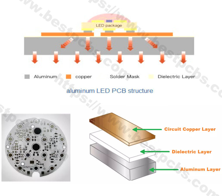
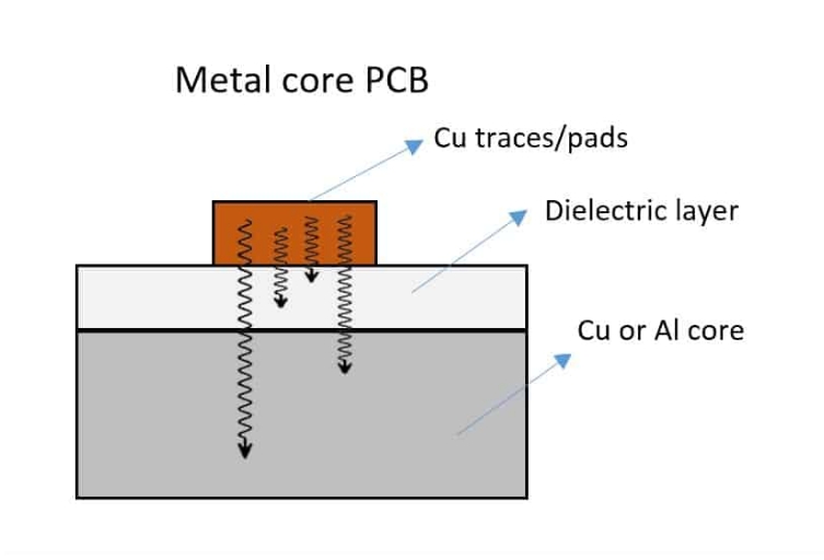
The power device is mounted on the circuit layer. The heat generated by the device during operation is quickly transferred to the metal base layer through the insulating layer, and then the metal base layer transfers the heat to achieve heat dissipation of the device.

Compared with the traditional FR-4, the aluminum substrate can reduce the thermal resistance to the minimum, making the aluminum substrate have excellent thermal conductivity; compared with the thick film ceramic circuit, its mechanical properties are extremely good.

In the circuit design scheme, the heat diffusion is handled very effectively, thereby reducing the module operating temperature, extending the service life, and improving the power density and reliability; reducing the assembly of the heat sink and other hardware (including thermal interface materials), reducing the product volume, and reducing the hardware and assembly costs; combining the power circuit and the control circuit

How to make a LED light circuit board?

Step 1: Design Your LED PCB:
Using PCB design software, create a schematic for your LED circuit and design the PCB layout, considering component placement and signal flow.

Step 2: Choose the Materials:
Select a suitable substrate material and copper-clad board based on your project requirements.

Step 3: Transfer the Design:
Print your PCB layout onto a special transfer paper and transfer it onto the copper-clad board using a heat press.

Step 4: Etch the Board:
Immerse the board in an etching solution to remove the excess copper and reveal the copper traces.

Step 5: Drill Holes:
Drill holes on the board to accommodate the LED chips and other components.

Step 6: Solder the Components:
Carefully solder the LED chips and other components onto the board, ensuring secure connections.

Step 7: Test Your LED PCB:
Connect your LED PCB to a power source and test the LEDs to ensure they light up correctly.

How to make a LED light circuit board?

Capabilities of led ring light pcb?

ItemCapabilities
Layer Count1 – 10 Layers
Max Board Dimension24*64″(610*1625mm)
Min Board Thickness0.6mm
Max Board Thickness4.0mm
Conductor Thickness0.5oz – 10oz
Min Line Width/Line Space4/4mil (0.10/0.10mm)
Min Hole Diameter10mil (0.25mm)
Min Punch Hole Dia0.12″ (3.0mm)
Min Hole Spacing16mil (0.4mm)
Min PAD Ring(Single)3mil (0.075mm)
PTH Wall ThicknessNormal: 0.59mil (15um); HDI: 0.48mil (12um)
Min Solder PAD Dia14mil (0.35mm)
Min Soldermask Bridge8mil (0.20mm)
Min BAG PAD Margin5mil (0.125mm)
PTH/NPTH Dia TolerancePTH: ±3 mil (0.075mm); NPTH: ±2mil (0.05mm)
Hole Position Deviation±3mil (0.075mm)
Outline ToleranceCNC: ±6 mil (0.15mm); Die Punch: ±6 mil (0.1mm)
Max Aspect Ratio10:01
Surface TreatmentENIG, Flash Gold, Hard Gold Finger, Gold Plating(50mil), Gold finger,
Selected Gold Plating, ENEPIG, ENIPIG, HAL, HASL(LF), OSP, Silver Imm., Tin Imm
Capabilities

Applications of led ring light pcb?

  1. Application in medical equipment
    The rapid progress of medicine is closely related to the rapid development of the electronics industry. Many medical devices are made of basic PCBs alone, such as pH meters, heart rate sensors, temperature measurements, electrocardiographs, electroencephalographs, MRIs, X-ray machines, CT scanners, blood pressure machines, blood sugar level measuring equipment, etc.
  2. Application in industrial equipment
    PCBs are widely used in manufacturing, especially in industries with high-power mechanical equipment; these devices run on high power and require high current circuit drive. Such as arc welding, large servo motor drives, lead-acid battery chargers, clothing cotton machines, etc.
  3. Application in lighting
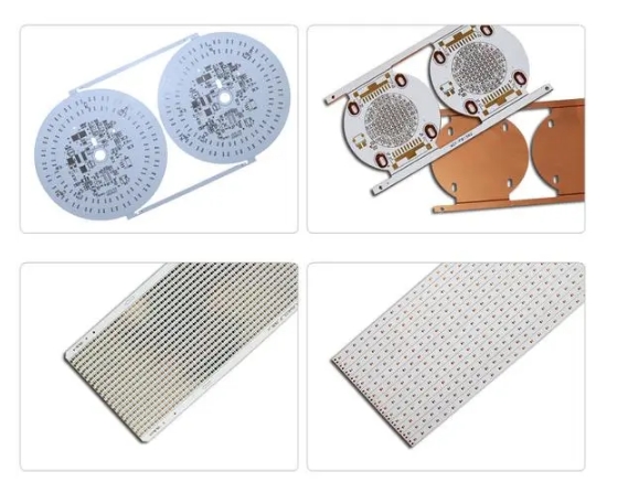
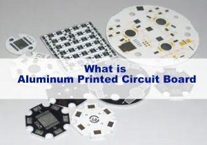
    LED lights and high-intensity LEDs are mounted on PCBs based on aluminum substrates; aluminum has the property of absorbing heat and dissipating it in the air.
  4. Application in the automotive and aerospace industries
    Flexible PCBs are lightweight but can withstand high vibrations. Because of their light weight, they can reduce the total weight of spacecraft; flexible PCBs can be adjusted even in narrow spaces. These flexible PCBs are used as connectors, interfaces, and can be assembled even in compact spaces

FAQs About led ring light pcb

What is the thermal conductivities and withstanding voltages of BT/FR4 layer and Dielectric layer?
The SinkPAD conducts heat primarily through the copper base (400W/m.K), the withstanding voltages of Dielectric layer is around 4KV.

What is the placement accuracy for the SMT components?
+/-0.05mm is our SMT accuracy tolerance. You are welcome to come to our SMT factory in Shenzhen China and Vietnam.

Can the aluminum be made as the base of sinkpad MCPCB?

Actually, the sinkpad can only use copper as the base.
As you can see the below manufacturing steps, the SinkPad will etch the copper base into convex platform with Copper Etching Solution, then hollow out the Double Layer FR4 PCB, and do lamination with the convex platform.
However, regarding of current technical conditions, since aluminum or aluminum alloy cannot directly react with acid, the reaction process is too complex and difficult to control, which will increase the difficulty of etching the LED pad platform. Considering the scrap rate, the process of etching LED pad platform with aluminum is more complex and the overall cost is higher.

Can I plated copper in mcpcb via holes?
Generally speaking, copper plating through holes requires hole rings, otherwise the copper in the hole wall will easily fall off.

In addition, if it is a copper substrate, through the hole first to resin plug before copper plating. 

Otherwise there’s no chemical reaction between copper and copper. And if the copper layer is connected to each copper layer, it is easy to short circuit.

Are you UL certified led pcb manufacturer?

Yes, we are UL certified manufacturer, our UL is E475635. We have already passed UL certificated. Meanwhile, we are passed ISO9001, ISO13485 and IATF16949 certifications. 

Our LED pcbs are manufactured under highly monitored by these quality system controls.

How does the conveity of sinkpad manufactured?

Actually the sinkpad can only use copper as the base.

As you can see the below manufacturing steps, the SinkPad will etch the copper base into convex platform with Copper Etching Solution, then hollow out the Double Layer FR4 PCB, and do lamination with the convex platform.However, regarding of current technical conditions, since aluminum or aluminum alloy cannot directly react with acid, the reaction process is too complex and difficult to control, which will increase the difficulty of etching.

You may also like

What Is led light pcb?
Friday, August 2nd, 2024

led light pcb , or printed circuit board, is a stable carrier of electronic components. It not only realizes electrical connection but also plays a supporting role. As the core component of electronic products, it is widely used in various electronic devices. In the field of LED lighting, PCB light board provides support and power for LED lamp beads, ensuring their stable operation in scenes such as home, commercial and automotive lighting. PCB with LED is often used to manufacture electronic products such as indicator lights, lighting equipment and display screens. The LED lamp beads on these PCBs are usually precisely soldered by SMT (surface mount technology).

What Is led light pcb?

led light pcb

LED PCB light board leads the development of the lighting industry with its innovative design, high efficiency and flexibility, bringing a more intelligent and comfortable lighting experience to our lives. It is not only an integrated platform for electronic components, but also a perfect combination of modern technology and aesthetics, and is the focus of future lighting trends.

Why use mcpcb for led light pcb

With the continuous development of LED technology, the heat generated by LEDs has gradually increased. The traditional FR4 printed circuit board (PCB) has been unable to meet the heat dissipation requirements due to its low thermal conductivity (only 0.36W/m.K). In order to solve this problem, the metal core printed circuit board (MCPCB) was proposed. It attaches the original printed circuit board to a metal with better thermal conductivity (such as aluminum and copper) to enhance the heat dissipation effect. The thermal conductivity efficiency of MCPCB is higher than that of traditional FR4 PCB, reaching 1W/m.K to 2.2W/m.K, which effectively improves the heat dissipation performance of LED PCB.

In addition, the use of MCPCB can also reduce the number of LEDs required to generate lighting, making it an ideal choice for street lights, automotive LED applications, and backlight unit applications. The use of metal substrates has practical advantages in heat dissipation, thermal conductivity, reliability, and electrical insulation, especially in harsh environments, and can also achieve reliable operation of LEDs. For example, using a metal substrate can reduce the LED junction temperature by 20-30°C, improve light output and enhance the overall performance of the product, ensure consistent UV light generation, and expand the possibilities of UV applications in various industries.

Why use mcpcb for led light pcb

Why use mcpcb for led light pcb

Advantages of led light pcb?

High thermal conductivity: LED PCB, especially aluminum substrate, uses aluminum alloy material with high thermal conductivity, which can effectively conduct away the heat generated by LED, maintain the stability of LED operation and extend the service life. This high thermal conductivity is essential to prevent heat accumulation and keep LED working at high brightness for a long time.

High efficiency: Compared with traditional incandescent lamps and energy-saving lamps, LED lamps have higher luminous efficiency and can provide better lighting effects while reducing energy consumption. This makes LED PCB have significant advantages in energy saving and environmental protection.

Long life: The service life of LED PCB far exceeds that of traditional lighting products, and it can provide longer continuous lighting, reducing the trouble of frequent bulb replacement and reducing maintenance costs.

Low energy consumption: LED PCB requires much less electricity than traditional lighting equipment while providing the same brightness, which is very important for energy saving, emission reduction and sustainable development

How does led light pcb dissipate heat?

The power device is mounted on the circuit layer. The heat generated by the device during operation is quickly transferred to the metal base layer through the insulating layer, and then the metal base layer transfers the heat to achieve heat dissipation of the device. Compared with the traditional FR-4, the aluminum substrate can reduce the thermal resistance to the minimum, making the aluminum substrate have excellent thermal conductivity; compared with the thick film ceramic circuit, its mechanical properties are extremely good. In the circuit design scheme, the heat diffusion is handled very effectively, thereby reducing the module operating temperature, extending the service life, and improving the power density and reliability; reducing the assembly of the heat sink and other hardware (including thermal interface materials), reducing the product volume, and reducing the hardware and assembly costs; combining the power circuit and the control circuit

How to make a LED light circuit board?

  1. Cutting
  2. Cutting process Picking materials – cutting
  3. The purpose of cutting
    Cut the large-sized incoming materials into the size required for production
  4. Precautions for cutting
    â‘  Check the size of the first piece of material
    â‘¡ Pay attention to the scratches on the aluminum surface and the copper surface
    â‘¢ Pay attention to the delamination and flash of the board edge
  5. Drilling
  6. Drilling process
    Pinning – drilling – board inspection
  7. The purpose of drilling
    Positioning and drilling holes in the board to assist the subsequent production process and customer assembly
  8. Precautions for drilling
    â‘  Check the number of holes and the size of the holes
    â‘¡ Avoid scratches on the board
    â‘¢ Check the flash of the aluminum surface and the hole position deviation
    â‘£ Check and replace the drill bit in time
    ⑤ Drilling is divided into two stages, one drilling: drilling holes after cutting for peripheral tool holes
    Second drilling: tool holes in the unit after solder mask
  9. Dry/wet film imaging
  10. Dry/wet film imaging process
    Grinding board – film pasting – exposure – development
  11. Purpose of dry/wet film imaging
    To present the part required for making circuits on the board
  12. Precautions for dry/wet film imaging
    â‘  Check whether the circuit is open after development
    â‘¡ Whether the development alignment is biased to prevent the generation of dry film fragments
    â‘¢ Pay attention to the circuit defects caused by scratches on the board
    â‘£ No air should remain during exposure to prevent poor exposure
    ⑤ After exposure, it should be still for more than 15 minutes before development
    IV. Acid/alkaline etching
  13. Acid/alkaline etching process
    Etching-film stripping-drying-board inspection
  14. Purpose of acid/alkaline etching
    After imaging the dry/wet film, keep the required circuit part and remove the excess part outside the circuit. During acid etching, attention should be paid to the corrosion of the etching solution to the aluminum substrate;
  15. Precautions for acid/alkaline etching
    â‘  Pay attention to incomplete etching and excessive etching
    â‘¡ Pay attention to line width and line thickness
    â‘¢ Oxidation and scratches are not allowed on the copper surface
    â‘£ The dry film should be removed cleanly
    V. Silk screen solder mask and characters
  16. Silk screen solder mask and character process
    Silk screen-pre-bake-exposure-development-characters
  17. Purpose of silk screen solder mask and characters
    â‘  Anti-soldering: protect circuits that do not need soldering and prevent tin from entering and causing short circuits
    â‘¡ Characters: serve as markings
  18. Precautions for silk screen solder mask and characters
    â‘  Check whether there is garbage or foreign matter on the board
    â‘¡ Check the cleanliness of the stencil â‘¢ Pre-bake for more than 30 minutes after silk screen printing to avoid bubbles in the circuit
    â‘£ Pay attention to the thickness and uniformity of the silk screen
    ⑤ After pre-bake, the board should be completely cooled to avoid film contamination or damage to the glossiness of the ink surface
    â‘¥ Place the ink side down during development
    VI. V-CUT, gong board
  19. V-CUT, gong board process
    V-CUT——gong board——tear protective film——remove burrs
  20. Purpose of V-CUT, gong board
    â‘  V-CUT: Cut the single PCS circuit and the entire PNL board to leave a small part connected for easy packaging and removal
    â‘¡ Gong board: remove the excess part of the circuit board
  21. Precautions for V-CUT, gong board
    â‘  During the V-CUT process, pay attention to the size of the V, the incompleteness and burrs of the edges
    â‘¡ Pay attention to the burrs caused by the gong board, the gong knife is tilted, and the gong knife is checked and replaced in time
    â‘¢ Finally, avoid scratches on the board when removing the burr
    VII. Testing, OSP
  22. Testing, OSP process
    Circuit test-voltage resistance test-OSP
  23. Testing, the purpose of OSP
    â‘  Circuit test: Check whether the completed circuit is working normally
    â‘¡ Voltage resistance test: Check whether the completed circuit can withstand the specified voltage environment
    â‘¢ OSP: Allow the circuit to be soldered better
  24. Testing, OSP precautions
    â‘  How to distinguish and store qualified and unqualified products after testing
    â‘¡ Placement after OSP
    â‘¢ Avoid damage to the circuit
    VIII. FQC, FQA, packaging, shipment
  25. Process
    FQC-FQA-packaging-shipping
  26. Purpose
    â‘  FQC conducts full inspection and confirmation of the product
    â‘¡ FQA spot check and verification
    â‘¢ Pack and ship to customers as required
  27. Note
    â‘  FQC should pay attention to the appearance confirmation during the visual inspection and make reasonable distinctions
    â‘¡ FQA should conduct random inspections to verify the inspection standards of FQC
    â‘¢ Confirm the packaging quantity to avoid mixed boards, wrong boards and packaging damage

Capabilities of led light pcb?

ItemCapabilities
Layer Count1 – 10 Layers
Max Board Dimension24*64″(610*1625mm)
Min Board Thickness0.6mm
Max Board Thickness4.0mm
Conductor Thickness0.5oz – 10oz
Min Line Width/Line Space4/4mil (0.10/0.10mm)
Min Hole Diameter10mil (0.25mm)
Min Punch Hole Dia0.12″ (3.0mm)
Min Hole Spacing16mil (0.4mm)
Min PAD Ring(Single)3mil (0.075mm)
PTH Wall ThicknessNormal: 0.59mil (15um); HDI: 0.48mil (12um)
Min Solder PAD Dia14mil (0.35mm)
Min Soldermask Bridge8mil (0.20mm)
Min BAG PAD Margin5mil (0.125mm)
PTH/NPTH Dia TolerancePTH: ±3 mil (0.075mm); NPTH: ±2mil (0.05mm)
Hole Position Deviation±3mil (0.075mm)
Outline ToleranceCNC: ±6 mil (0.15mm); Die Punch: ±6 mil (0.1mm)
Max Aspect Ratio10:01
Surface TreatmentENIG, Flash Gold, Hard Gold Finger, Gold Plating(50mil), Gold finger,
Selected Gold Plating, ENEPIG, ENIPIG, HAL, HASL(LF), OSP, Silver Imm., Tin Imm

Applications of led light pcb?

  1. Application in medical equipment
    The rapid progress of medicine is closely related to the rapid development of the electronics industry. Many medical devices are made of basic PCBs alone, such as pH meters, heart rate sensors, temperature measurements, electrocardiographs, electroencephalographs, MRIs, X-ray machines, CT scanners, blood pressure machines, blood sugar level measuring equipment, etc.
  2. Application in industrial equipment
    PCBs are widely used in manufacturing, especially in industries with high-power mechanical equipment; these devices run on high power and require high current circuit drive. Such as arc welding, large servo motor drives, lead-acid battery chargers, clothing cotton machines, etc.
  3. Application in lighting
    LED lights and high-intensity LEDs are mounted on PCBs based on aluminum substrates; aluminum has the property of absorbing heat and dissipating it in the air.
  4. Application in the automotive and aerospace industries
    Flexible PCBs are lightweight but can withstand high vibrations. Because of their light weight, they can reduce the total weight of spacecraft; flexible PCBs can be adjusted even in narrow spaces. These flexible PCBs are used as connectors, interfaces, and can be assembled even in compact spaces

You may also like

Do You Know What a Metal Core PCB Is?
Saturday, February 25th, 2023

Metal Core Printed Circuit Board (short for MCPCB) is a technology developed to overcome the thermal limitations of the FR4 Printed Circuit Board. Different with traditional FR4 PCB, the PCB uses FR4 material as base core, while the base material of a metal core PCB is aluminum or copper. So compared with FR4 PCB, Metal Core is a better choice if your boards need to perform in high temperature environment.

What is metal core PCB?

A Metal Core PCB (MCPCB), also known as a thermal PCB or metal backed PCB, is a type of PCB that a metal material as its base for the heating dissipation part of the board. The thick metal is covering one side or double side of the PCB. The purpose of the core of a MCPCB is to redirect heat away from critical board components (such as LED or IC chips), and to less crucial areas such as the metal heatsink backing or metallic core. Base metals in the MCPCB are used as an alternative material to FR4 boards.

(Metal_core_PCB)

Same as FR4 PCB, the metal core PCB can be divided into Single layer MCPCB, Double layers MCPCB and Multi-layer MCPCB.

  • Single layer MCPCB

A single layer MCPCB is consist of a metal base (usually aluminum or copper alloy), thermal conductivity/dielectric layer and a copper trace layer, you can check below stack up for more details. Due to it only has one layer copper trace, sometimes we called it as one-layer MCPCB or single sided MCPCB.

(Stack_up_of_single_layer_MCPCB)

The single sided MCPCB can be used with surface mount and chip & wire components, and provides much lower thermal resistance than FR4 PCB. What’s more, the metal core provides lower cost than ceramic substrates, and allows much larger areas than ceramic substrates.

Meanwhile, superior heat dissipation and good durability of Aluminum of metal core PCB can greatly eliminate heat sinks or other some voluminous hardware for engineers or designers.

  • Double layer MCPCB

Double layers MCPCB (2L MCPCB) has two copper layers on one side of PCB, and metal core as a base core on the bottom side of whole MCPCB, so the components only can be populated on the top side, below is a structure of double layer MCPCB.

(Stack_up_of_double_layers_metal_core_PCB)

From the stack up of double layers MCPCB, we can see it consists of a single layer MCPCB and a double sided FR4 PCB, so it needs an additional pressing process to laminate the thermal conductivity and FR4 PCB. Compared with normal FR4, this structure needs more technology and experience on laminating of two layers together with metal core.

There are two layers copper trace on the surface of MCPCB, can we call it as double sided MCPCB like single layer MCPCB?

The answer is NO, because they have different structure and perform different properties. In our next post, we will show you the differences between double sided MCPCB and 2 layers MCPCB.

  • Multi-layer MCPCB

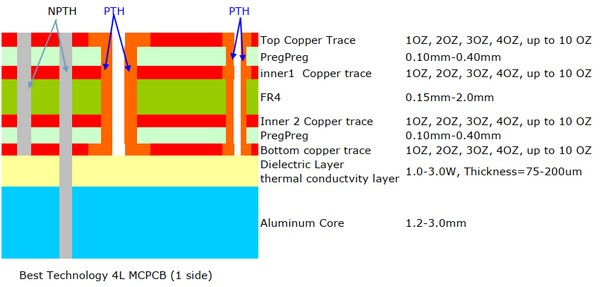
Same as FR4 PCB, for those copper traces more than 2 layers, we named them Multi-layer MCPCB. Its structure is same as FR4 PCB, but more complex to fabricate. Below is a typical stack up of a 4 layers MCPCB:

(Stack_up_of_4L_MCPCB)

Contrast with single layer or double layers MCPCB, multi-layer MCPCB can populate more components and achieve better performance in electronical performance.

Why Choose Metal core PCB?

Metal core PCB offers a great list of advantages when apply in a high-power application, below we listing some benefits of it:

  • Excellent heat dissipation
  • Lower thermal expansion than FR4 PCB
  • Dimensional stability than polyimide FPC
  • Great durability
  • Long lifetime
  • High utilization rate of space due to the heating can be transferred quickly
  • High strength and lightweight than FR4 PCB
  • Cost-effective

Where can we use Metal core PCB?

Metal core PCB can be used in high-power filed where requires fast cooling, good heat dissipation characteristics, the following popular applications may give you a guideline:

  • LED lighting
  • Power suppliers
  • Power conversion system
  • Automotive electronics
  • Telecom industrial
  • Photovoltaics
  • Semiconductors

With more than 16 years manufacturing experience, Best Technology is one of MCPCB supply leaders in Asia with good metal core PCB capability, we are so confident that we can provide you high quality, fast delivery and excellent one-stop service. Warm welcome to contact us if you have inquiries.

You may also like

Types of Metal Bases Utilized in MCPCB
Tuesday, May 10th, 2022

What is metal core printed circuit?

Metal core printed circuit board is abbreviated as MCPCB. And namely, the core or the base material of MCPCB is a metal instead of the traditional FR4/CEM1-3.

Types of metal bases used in MCPCB

The metal cores of the thermal PCB can be aluminum, copper and steel alloys. Apart from being cheaper than copper, aluminum is known for its good heat transferring and dissipation abilities, which is the most common used. However, copper is considered to be a better performer. So, why does the aluminum become the first choice for the material of the MCPCB?

Aluminum base—The aluminum PCB offers good heat dissipation and heat transferring ability. Since they are also light in weight, the aluminum core PCBs are widely used in LED products.

Aluminum Core PCB

Copper base—The copper core board features a better performance than aluminum. But customers will usually choose the aluminum instead of copper, for it is relatively expensive. Also, compared with the aluminum, the copper is heavier and involves a tough machining process.

Copper Core PCB

Various base metals and their properties

Metal Base MaterialThermal Conductivity
(W/m-K)
Coefficient of Thermal Expansion
(µm/m-°C)
Aluminum88-25125
Copper38617

Based on the table, it can be known that although the thermal conductivity of the copper is better than that of the aluminum, its ability of thermal expansion does not perform better than the aluminum.

Therefore, there are some reasons why the aluminum is the first choice for the material of the MCPCB, including the lower cost compared to copper, light weight, excellent durability and its heat transferring capabilities.

And these are also the reasons that the MCPCB is widely used in the LED products as we mentioned in the last article.

So, this is the end of this article. In case if you have any questions, you are welcome to contact us via email at  sales@bestpcbs.com. We are fully equipped to handle your PCB or MCPCB manufacturing requirements.

You may also like

Why is the MCPCB Widely Used in the LED Products?
Saturday, April 30th, 2022

MCPCB refers to metal core printed circuit board. It has a good performance in heat dissipation, so it is often used in LED products.

The advantages of MCPCB

Prevent overheating: 

LEDs tend to get overheated very quickly. If a metal core printed circuit board is used, it solves overheating by transferring the energy from one side to another.

Improve the material’s reliability: 

The MCPCB plays a key role in the elements that heats up overly at times. It helps to divert the heat from one side to another where the heat has vanished, which improves the product’s life, making it much more durable.

Adapt to a high temperature: 

Unlike the FR4 technology, the metal core printed circuit board can adapt to products with a high temperature, hence it proves to be very useful for LED products.

LED PCB

Why is the MCPCB widely used in the LED products?

Since it is well-known that the LED products will emit a lot of heat. Based on the advantages, the metal core PCB can transfer heat quickly and prevent overheating. And Aluminum PCB is mostly used in metal core PCBs, for they can operate longer than other metals and longer shelf life.

Moreover, metal core PCB has a high conductive ability, hence there remains ample space for maximum LEDs, which allows producing sufficient light and achieving high performance.

Therefore, based on the advantages of the MCPCB, it is the prior option of the material for the LED products.

So, this is the end of the article. In case if you have any questions, you are welcome to contact us via email at  sales@bestpcbs.com. We are fully equipped to handle your PCB or MCPCB manufacturing requirements.

You may also like

Differences in Structure——Aluminum PCB vs Ceramic PCB Series 1
Monday, March 21st, 2022

It is supposed that we are familiar with both aluminum PCB and ceramic PCB. But if juxtaposing them, which one will be better by one tally? So, we are about to talk about some differences between them in terms of structure.

Aluminum PCB

Aluminum substrate namely uses aluminum as substrate, which has a good heat dissipation capacity. Generally, it is single-sided, and also can be double-sided while multi-layer aluminum PCB is a little bit hard to manufacture. Besides, a single layer aluminum PCB is made up of copper layer, dielectric layer and aluminum layer.

Structure of Aluminum PCB

Ceramic PCB

Ceramic PCB namely uses ceramic as substrate. Apart from the material, the structure is the biggest difference between ceramic PCB and aluminum PCB. Since ceramic itself is an insulating material, it does not need a dielectric layer. Its structure is as follows.

Structure of Ceramic PCB

Therefore, whether there is a dielectric layer is the main difference in structure between aluminum PCB and ceramic PCB. And dielectric layer plays an important role in thermal conductivity. So, what is the relationship between dielectric layer and thermal conductivity? And whose thermal conductivity is better between aluminum PCB and ceramic PCB?

We will talk about it next time. And if you would like to know the answer, please feel free to contact us, or you can continuously follow our blog site, we will keep updating more information about the differences between aluminum PCB and ceramic PCB on it.

You may also like

What are the factors affecting cost of the MCPCB?
Tuesday, September 29th, 2020

Best Technology considers all the factors affecting the cost of MCPCB production while formulating final cost structure. Many customers contact us to know the factors which affecting the price. The factors are Size & Thickness, Number of layers, Cu Thickness, Thermal Conductivity, Surface Finishing etc.

Size & Thickness: Since larger boards require more material.

As you know, 1.6mm is the standard thickness, if you choose non-standar thickness (Thicker or thinner than 1.6mm), sometimes the price will need to increase, it depend on the layers of your MCPCB.

The different number of layers and manufacturer technology:It’s the main factor for affecting the manufacturing price, therefore the circuit board designing is done in such a manner that it comprises a minimum number of circuit layers. 

Thermal Conductivityis one of the most important performances of MCPCB, the higher the thermal conductivity is, the more expensive the price is. At present, the highest thermal conductivity we can provide is 8W/m.K, the commonly used thermal conductivity is 1-3W/m.K

Cu Thickness: The cost will be more expensive if the copper is thicker. We can provide 0.5 OZ, 1.0 OZ, 2.0 OZ, 3.0 OZ, up to 10 OZ.

Surface Finishing: The common Surface Finishing for MCPCB is HASL_LF, OSP  ENIG (The normal thickness of gold is 1u’’). ENIG is more expensive since the gold is expensive and it with good performance for protecting the surface from oxidized.

ENIEPIG is good for wire bonding (the normal thickness of gold is 3uâ€Â).

We always strive to formulate a competitive price structure for our customers, this enables to have a considerable reduction in the total prices and deliver superior quality services to them. If you would like to know more about MCPCB, please directly contact our sales Tammy

You may also like

What are the Differences between Double Sided MCPCB and Double/Two Layers MCPCB?
Friday, August 14th, 2020

Metal Core PCB are differentiated on the basis of their construction, which can be divided into following types: single layer, double/two layers, double sided, and multi layer. The double sided and double/two layers MCPCB are commonly used in advanced electronic circuits, some people may be confused about them due to their similar names. So in this blog I’d like to share with you the differences between the two types. 

Actually the main difference is the double sided and double/two layers MCPCB have different layout due to the positioning of the metal core.

Double/two layers MCPCB

As you can see the following stack up, the metal core is at the bottom, with two copper layers on top side, the dielectric layer is between the copper layer and the bottom metal base. In short, the conductor layers is in same side of the metal core. The components can only be assembled on the top layer.

double/two mcpcb stack up
double/two mcpcb

Double sidedMCPCB

As you can see the following MCPCB stack up, the metal core is in the middle of two conductor layers. There is also a dielectric layer between the metal core and a copper layer. The metal core and conductors are connected to each other through PTH (Plated Through Hole). The components can be assembled on both the bottom and top.

double sided mcpcb stack up
double sided mcpcb
Double sided MCPCB

Both double sided and double/two layers aluminum/copper core have the good heat dissipation, reliable performance at high temperatures and excellent thermal expansibility, according to our experience, for the same design, the heat dissipation on Double Sided MCPCB is a little better than Double Layers MCPCB.

The choice of the either type will depend on customer’s application requirements. If you are still confused about the two types and their benefits for your application, please feel free to contact Tammy (Email:sales9@bestpcbs.com), the Metal Core PCB International Sales in Best Technology.

Welcome to visit our website to learn more about us, we can provide different types of MCPCB in diverse specifications.

You may also like

What is SinkPad PCB?
Wednesday, June 17th, 2020

SinkPad PCB, also called Heat Sink or DTP (direct thermal path) PCB, it is a type of Copper base PCB used in thermoelectric separation application. It generally used for high power LED, the pad of LED touch the copper base directly, so that the heat generated by LED will dissipate quickly, which can achieve the best heat dissipation and conduction.

SinkPad PCB
SinkPad PCB

Thermoelectric separation technology is based on the higher heat dissipation requirements of high power electronic products, which needs to meet two basic conditions:

1.LED pad touches the base substrate directly.

It means we need to increase the path of the LED pad to the base substrate to accelerate the heat emission from the base material.

Two layers SinkPad PCB Stack up

2.Higher heat dissipation substrate materials

Copper has a thermal conductivity of 401W/m·K, while aluminum has a thermal conductivity of 237W/m·K. Obviously, copper has better thermal conductivity because of its high density, high mass. Therefore, a SinkPad PCB usually means a SinkPad copper base PCB.

You may also like

Why do High Power LED mostly use COB light sources? What are the advantages?
Tuesday, June 16th, 2020

If we observe carefully, we will find that most of the high-quality surface light lamps in the market use COB light source, such as LED spotlights, Automotive, LED Backlight for LED TV, etc. What are the advantages of such choice?

Automotive
Automotive
LED Backlight for LED TV
LED spotlights
LED spotlights

First of all, we need to how the COB differ from the common MCPCB. “Chip-On-Board” Metal Core PCB is a type of MCPCB used in thermoelectric separation application. By using COB, the micro-chip (also known as “die”) directly touch the metal core where the heat dissipate, and electrically interconnect the trace of circuit board (wire-bonding) so that power supply can be provided.

Stack up
Stack up

Advantages of utilizing COB MCPCB over common MCPCB:

  1. High thermal conductivity(137W/m.K), High insulation, High pressure resistance
  2. High reflectivity: mirror aluminum≥98% (The reflectivity of Taiyo Soldermask used in common MCPCB is 75-80%, the highest is only 90%)
aluminum pcb
BAS15191
metal core pcb
BAS15192

Since the COB is packaged directly on the MCPCB, it’s easy assembly for high powers LED, direct heat dissipation through the substrate can not only reduce the manufacturing process and cost of the bracket, but also have the advantage of reducing heat dissipation resistance. So the spotlight produced by COB technology will be lighter, more flexible and able to realize more possibilities on the stage.

If you are also interested in COB, please feel free to contact me, I’m looking forward to communicating more with you.

You’re welcome to visit our website to learn more about us. https://www.bestpcbs.com/products/COB-MCPCB.htm

You may also like