Why choose 94V0 LED PCB? Learn about material options, assembly steps, compliance checks, and rapid customization in flame-retardant PCB manufacturing.
Best Technology specialize in OEM 94V0 LED PCB assembly with UL-certified FR-4/aluminum substrates supporting 1-6oz copper layers. Our in-house tooling achieves 48-hour prototype turnaround for complex layouts (≤0.15mm trace/space). Advanced AOI/X-ray systems detect voids ≤15μm in thermal vias, ensuring IPC Class 3 reliability. Custom dielectric coatings (75-200μm) enable 4kV isolation for high-voltage drivers. We maintain ≤0.5% assembly defects through controlled reflow profiles (±2°C variance) and moisture-sensitive component baking. RoHS/REACH-compliant processes integrate seamlessly with global LED supply chains, delivering bulk orders in 12-18 days via pre-certified material stock. Contact us today sales@bestpcbs.com if you have any request for 94V0 LED PCB.
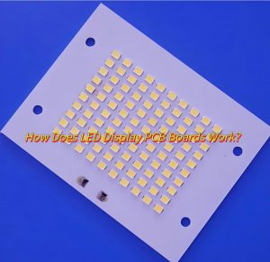
What Is A 94v0 LED PCB?
A 94V0 LED PCB is a printed circuit board designed for LED applications that meets the UL 94 V-0 flammability rating. This standard certifies the material self-extinguishes within 10 seconds of ignition and prevents flaming drips, making it suitable for high-heat or safety-sensitive environments. These PCBs often use flame-retardant substrates like FR-4 or aluminum to ensure reliability in LED systems while complying with strict fire-safety regulations. The designation “94V0” specifically refers to the board’s ability to resist combustion and minimize fire risks in electrical.
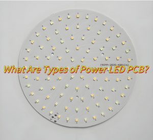
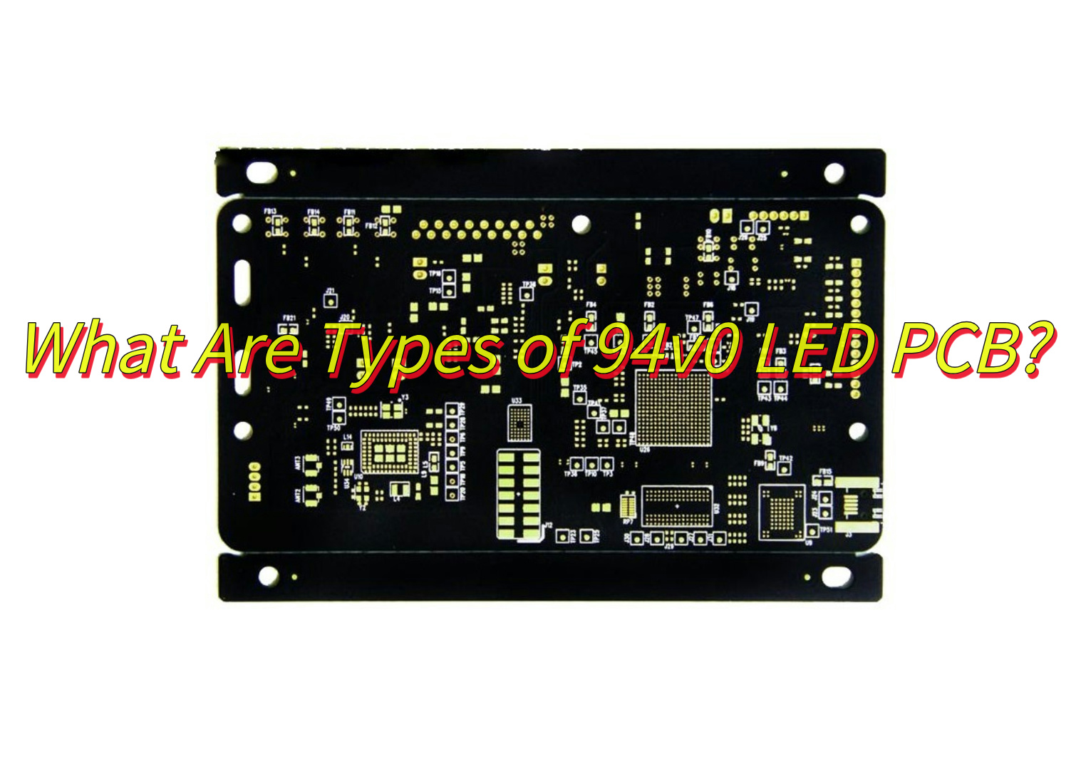
What Are Types of 94v0 LED PCB?
Types of 94V0 LED PCB:
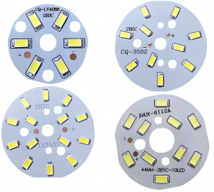
- FR-4 94V0 PCB: Flame-retardant glass-reinforced epoxy laminate, widely used for standard LED lighting due to balanced cost and durability.
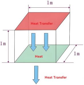
- Aluminum-core 94V0 PCB: Combines aluminum substrates with 94V0-rated dielectrics, ideal for high-power LED systems requiring heat dissipation up to 2.2 W/m·K.
- CEM-3 94V0 PCB: Composite epoxy material with woven glass surfaces, a cost-effective option for double-sided LED boards in mid-range applications.
- 94V0 Paper-based PCB: Uses phenolic resin-impregnated cellulose paper, suitable for low-cost LED indicators or non-critical lighting fixtures.
- Ceramic-filled 94V0 PCB: Integrates ceramic particles into substrates for enhanced thermal stability in high-temperature LED environments.
- Metal-core 94V0 PCB: Steel or copper bases with flame-retardant layers, used in automotive LED lighting for vibration resistance.
- Polyimide 94V0 Flexible PCB: Bendable circuits with flame-retardant coatings, applied in curved LED strips or wearable lighting.
- Hybrid 94V0 PCB: Layers FR-4 and aluminum materials to optimize thermal performance and cost for industrial LED modules.
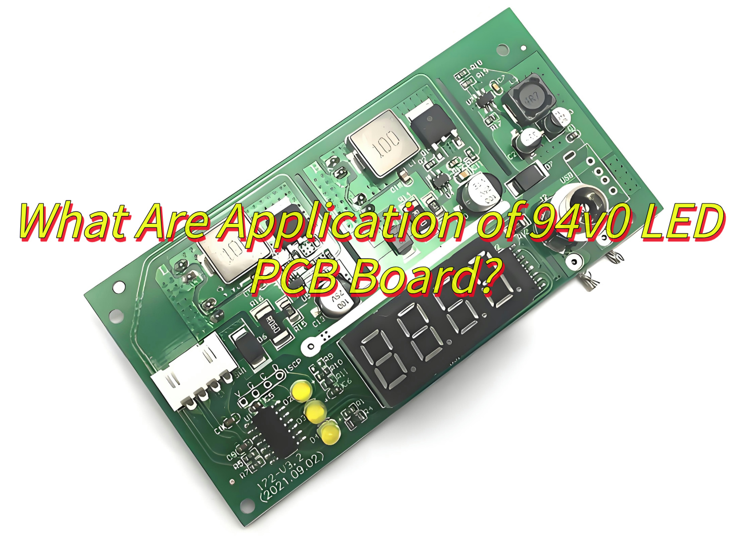
What Are Application of 94v0 LED PCB Board?
Here are practical applications of 94v0 LED PCB boards:
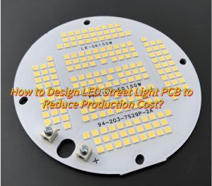
High-power LED lighting
- Used in streetlights, high-bay industrial lights, and floodlights where thermal management is critical.
Commercial signage and displays
- Found in digital billboards, menu boards, and LED video walls requiring long-lasting performance.
Automotive LED systems
- Applied in headlights, tail lights, and interior cabin lighting needing shock-resistant and temperature-stable designs.
Outdoor architectural lighting
- Employed in building facades, bridges, and public art installations exposed to moisture and UV radiation.
Medical LED equipment
- Integrated into surgical lights, diagnostic tools, and sterilization devices requiring precise thermal control.
Emergency vehicle lighting
- Used in police, fire, and ambulance warning systems needing vibration-resistant and rapid-response circuits.
Agricultural grow lights
- Deployed in vertical farms and greenhouses for spectrum-optimized LED arrays with uniform heat distribution.
Marine navigation lighting
- Installed in ships and offshore platforms requiring corrosion-resistant materials and compliance with maritime standards.
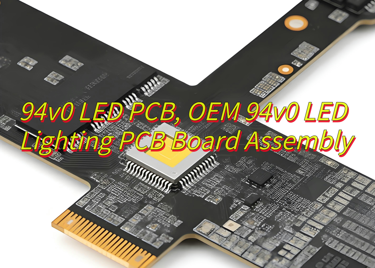
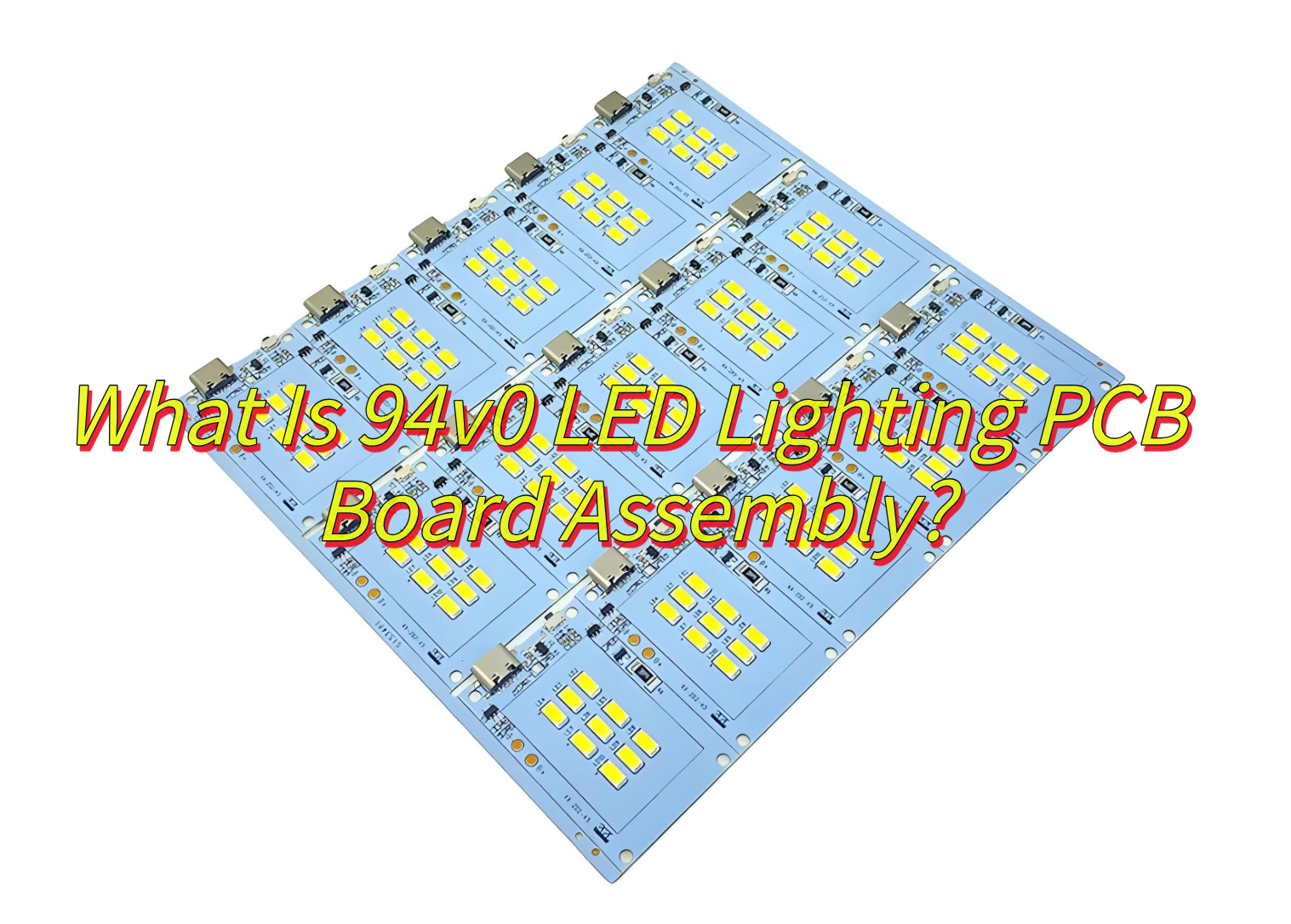
What Is 94v0 LED Lighting PCB Board Assembly?
A 94V0 LED lighting PCB assembly refers to the process of mounting and soldering electronic components (LEDs, resistors, connectors) onto a printed circuit board (PCB) made from materials meeting the UL 94V-0 flammability rating. This standard confirms the PCB substrate self-extinguishes within 10 seconds when exposed to flames, preventing fire spread. The assembly involves automated SMT (surface-mount technology) or manual through-hole soldering, followed by thermal stress tests and electrical validation to ensure stable performance under high heat or humidity. Compliance with 94V0 ensures the final product meets safety regulations for environments where fire hazards must be minimized.
What Are the Steps in A 94V0 Aluminum LED Circuit PCB Assembly?
Steps in a 94V0 Aluminum LED Circuit PCB Assembly:
1. Substrate selection
- Use aluminum-core PCBs with UL 94V-0 certification to meet flame-retardancy requirements and thermal conductivity needs.
2. Surface insulation treatment
- Apply ceramic-filled polymer coatings to electrically isolate the circuit layer from the aluminum base, preventing short circuits.
3. Solder paste printing
- Deposit lead-free solder paste using stencils designed for aluminum’s thermal expansion coefficient to avoid warping.
4. Component mounting
- Place LEDs, drivers, and SMD resistors via high-precision pick-and-place machines, ensuring alignment on the rigid aluminum surface.
5. Controlled reflow soldering
- Process boards in reflow ovens with peak temperatures ≤240°C to prevent dielectric layer delamination.
6. Thermal management integration
- Attach adhesive-backed heatsinks or thermal pads directly to the aluminum substrate for enhanced heat dissipation.
7. Automated optical inspection
- Use 3D AOI systems to detect solder defects, component misalignment, or insufficient paste coverage.
8. Electrical validation
- Test circuit continuity, LED brightness consistency, and driver output stability using programmable power supplies.
9. Environmental stress testing
- Subject boards to 85°C/85% RH conditions for 48+ hours to verify material stability and solder joint reliability.
10. Compliance verification
- Inspect final assemblies for RoHS compliance, coating uniformity, and mechanical durability per industry standards.
How to Verify Quality in 94V0 LED Metal Core PCB Assembly?
Methods to Verify Quality in 94V0 LED Metal Core PCB Assembly:
Surface insulation resistance test
- Measure resistance between the circuit layer and aluminum base using a megohmmeter (>100MΩ at 500VDC), confirming dielectric coating integrity.
Thermal cycling validation
- Cycle boards between -40°C and +125°C for 100+ cycles to check for solder joint cracks or material delamination.
Flame retardancy verification
- Perform UL 94V-0 vertical burn test: expose samples to open flame for 10 seconds, ensuring self-extinguishing within 10 seconds after removal.
Solder joint X-ray inspection
- Use 2D/3D X-ray systems to detect hidden defects like voids in thermal vias or insufficient solder under components.
Thermal imaging analysis
- Operate LEDs at maximum current while capturing infrared images to verify uniform heat distribution across the aluminum core.
High-potential testing
- Apply 1500V AC for 60 seconds between conductive layers to identify insulation breakdown or dielectric weaknesses.
Coating thickness measurement
- Use eddy current gauges to verify dielectric layer consistency (typically 75-150μm) across the PCB surface.
Mechanical stress evaluation
- Perform 24-hour vibration testing (5-500Hz frequency sweep) to confirm component retention and joint durability.
Chemical compatibility check
- Immerse samples in LED cleaning solvents for 24 hours, then inspect for coating degradation or discoloration.
Luminance consistency audit
- Measure light output uniformity across all LEDs using spectroradiometers, ensuring <5% variance in correlated color temperature.
Can OEMs Customize 94V0 LED Lighting PCB Assembly?
Yes, OEMs can customize 94V0 LED lighting PCB assembly to meet specific needs. Here’s how:
Design Flexibility
- OEMs adjust PCB dimensions, layer stacks, and component placement based on customer specifications.
Material Options
- Offer choices between aluminum, copper, or FR-4 substrates with 94V0 ratings to suit thermal and mechanical requirements.
Component Integration
- Allow customization of LED types, drivers, and additional components (sensors, connectors) to match application demands.
Process Optimization
- Tailor assembly processes—manual vs. automated—to balance cost, volume, and turnaround time.
Certification Assistance
- Support compliance with regional standards (UL, CE, etc.) by designing PCBs to meet specific certification criteria.
Testing Protocols
- Implement customized testing regimens (thermal cycling, vibration, longevity) to validate performance in unique environments.
Packaging Solutions
- Provide specialized packaging (ESD-safe, moisture-resistant) to protect PCBs during shipping and storage.
OEMs work closely with clients to ensure every aspect of the PCB assembly—from design to delivery—aligns with their exact requirements.
How Fast Can 94v0 PCB Assemblies Be Customized?
Production Timeline for 94V0 PCB Assembly Customization:
Design validation
- Engineers review schematics and thermal requirements for LED layouts, typically requiring 2-5 business days.
Material procurement
- Standard FR-4 substrates: 3-7 days.
- Custom aluminum cores with dielectric coatings: 10-15 days.
- Specialty solder masks (e.g., reflective white): 7-10 days.
Tooling preparation
- Stencil fabrication and test jig development for aluminum PCB profiles take 3-5 days after design freeze.
Prototype assembly
- Small batches (5-20 units) with basic testing complete in 4-7 days, excluding complex thermal validation.
Certification testing
- UL 94V-0 flammability and thermal shock tests add 8-12 days for third-party lab scheduling and reporting.
Volume production
Automated lines process 500-1,000 boards/day after setup, with throughput limited by:
- Aluminum substrate drilling speed (20-40 seconds/hole)
- Thermal via fill and curing time (2-4 hours/lot)
Shipping logistics
- Air freight reduces transit to 3-5 days globally; sea freight adds 18-30 days for bulk orders.
Acceleration Methods
- Pre-certified materials reduce validation by 6-8 days
- Parallel processing of solder mask curing and component sourcing saves 3 days
- On-site UL testing labs cut certification time to 72 hours
By aligning these factors, OEMs can deliver customized 94v0 PCB assemblies efficiently while maintaining quality and compliance.