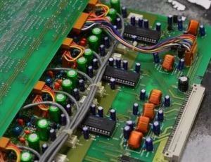
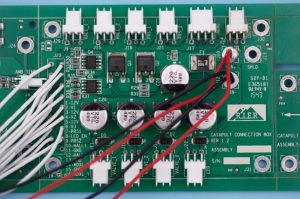
PCB rework is a delicate yet vital process for restoring functionality to circuit boards with flaws or damages. It involves methodically removing, replacing, or modifying components to correct issues. Whether itās due to design alterations, assembly errors, or minor repairs, PCB rework can save costs and prevent discarding entire units
What is the Process of PCB Rework?
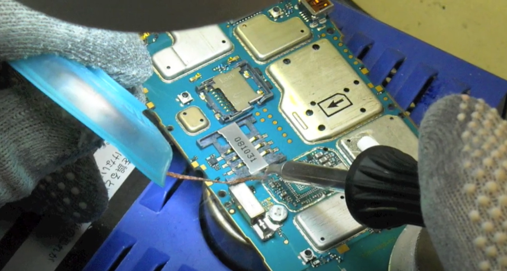
The process of PCB rework generally follows a series of careful steps. Technicians start by inspecting the board to identify the defective areas. For rework, precise tools like soldering irons, hot air rework stations, or BGA rework machines are typically used.
Once heated, damaged or defective components are removed. A flux application ensures that the solder flows cleanly, which reduces the risk of bridging or insufficient connections. The next step is carefully placing a new component in place, using a microscope to ensure accuracy, particularly for small parts like surface-mount components. Finally, the connections are resoldered, and the board undergoes cleaning and testing.
What is the Difference Between Repair and Rework in PCB?
PCB repair and rework, though closely related, serve unique purposes within electronics manufacturing and servicing. Rework refers specifically to correcting issues in a PCB due to assembly errors or modifications required before the board is shipped to the customer. This process should be operated very carefully, including during removing, adjusting, or replacing components. For instance, rework might be needed if components were placed incorrectly, solder joints are weak, or the board has minor assembly defects.
Repair, however, addresses boards that have become faulty or non-functional after use. Repair focuses on bringing a board back to working condition, whether due to physical damage, such as broken traces or burnt components, or due to environmental factors like corrosion. While rework ensures the board meets its initial design intent, repair aims to recover a boardās functionality after it has failed. Both repair and rework require precise techniques and skilled technicians, but repair can be more complex due to the nature of post-production or operational damages.
In summary:
- Rework: Fixing pre-delivery assembly issues to align the board with its intended design.
- Repair: Restoring functionality to a damaged or non-functional board, often due to wear, damage, or environmental exposure.
How Many Times Can You Rework a PCB?
The number of rework attempts a PCB can safely endure depends on factors like the materials used in the board, the board’s structure (e.g., number of layers), and the rework methods applied. Typically, each rework cycle subjects the board to a heating process, which can wear down solder joints and laminate strength over time. For most PCBs, rework should be limited to two or three cycles to avoid degradation, as repeated heating can lead to pad lifting, warping, or delamination of the substrate, especially with multi-layer boards.
Multilayer PCBs with multiple embedded connections are particularly sensitive, as excessive heating can damage internal layers. High-temperature cycles weaken solder joints, increasing the risk of electrical faults. Some high-quality boards, particularly those designed for critical applications like aerospace or medical devices, may tolerate additional rework if built with durable materials, but general guidance suggests minimal rework attempts. Careful planning and accurate diagnostics are essential for minimizing rework cycles, ensuring the boardās lifespan is preserved.
Can a Damaged PCB Be Repaired?
Yes, in many cases, a damaged PCB can be repaired.
It depends on the type and extent of the damage. For example, broken traces, lifted pads, and minor component failures are often fixable. Using epoxy, technicians can repair lifted pads, while trace repair kits can restore broken connections. However, severe burns or extensive damage to multiple layers can make repairs impractical or costly. The best approach is to assess each situation individually and determine if repair is viable.
What Wire is Best for PCB Rework?
Using the right wire during PCB rework is crucial for achieving reliable connections. For rework, thin, lead-free solder wire with a flux core is often recommended. A wire diameter of 0.5mm to 0.8mm provides better control and precision, making it suitable for both small and large components. Lead-free solder is preferred in many industries due to environmental regulations, but it requires higher temperatures than traditional lead-based solders, so itās essential to have proper temperature control.
Flux-core solder wire is essential as it allows for smoother, more reliable connections by promoting better solder flow and reducing oxidation at solder joints. Rosin-core flux is commonly used because it provides a strong bond and requires minimal cleaning. Additionally, if jumper wires are needed to bridge broken traces, insulated 30 AWG wire is ideal due to its fine gauge.
What is the IPC Standard for PCB Rework?
The IPC standards for PCB rework and repair are widely recognized and adhered to within the electronics industry to ensure quality and reliability. IPC-7711 and IPC-7721 specifically address rework, modification, and repair of printed circuit boards.
- IPC-7711 provides guidelines for reworking and modifying electronic assemblies. This includes instructions on tools, temperature control, and safety practices necessary for removing and replacing components while preserving the boardās structure. It offers details on soldering and desoldering techniques that ensure high-quality connections after rework.
- IPC-7721 focuses on the repair aspect, covering methods for handling damaged components and structural faults like broken traces, lifted pads, and substrate repair. This standard is critical for technicians performing repairs, as it outlines best practices for restoring physical and electrical integrity without compromising board function.
What is the Main Cause of PCB Failure?
PCB failures may cause from a variety of factors, with design flaws, manufacturing errors, and environmental stresses among the primary culprits. Hereās a closer look at some of the main causes:
- Design Flaws: Poorly optimized PCB layouts can lead to issues like excessive heat buildup, inadequate trace width for current capacity, or improper component spacing.
- Manufacturing Errors: Mistakes during the assembly process, such as improper soldering temperatures or placement inaccuracies, can lead to weak solder joints or misaligned components. These issues may not be apparent initially but can result in premature board failure.
- Environmental Stress: PCBs exposed to extreme temperatures, humidity, or corrosive environments are at risk of damage. Moisture can cause short circuits or corrosion on solder joints and traces, while high temperatures may warp the board or degrade the substrate. Boards used in outdoor or industrial settings are especially vulnerable.
- Electrostatic Discharge (ESD): Sensitive components can fail if exposed to static electricity.
- Aging and Wear: Over time, boards and components naturally wear out. Solder joints may crack, components degrade, and thermal cycles lead to material fatigue.
If your PCB or PCBA canāt work, and donāt know where is the problem. You can contact Best Team to ask for help, we are professional in this industry.


