pcb
Home > Blog

Posts Tagged ‘pcb thickness’

What is 0.4mm thickness PCB? Ultrathin PCB
Thursday, January 9th, 2025

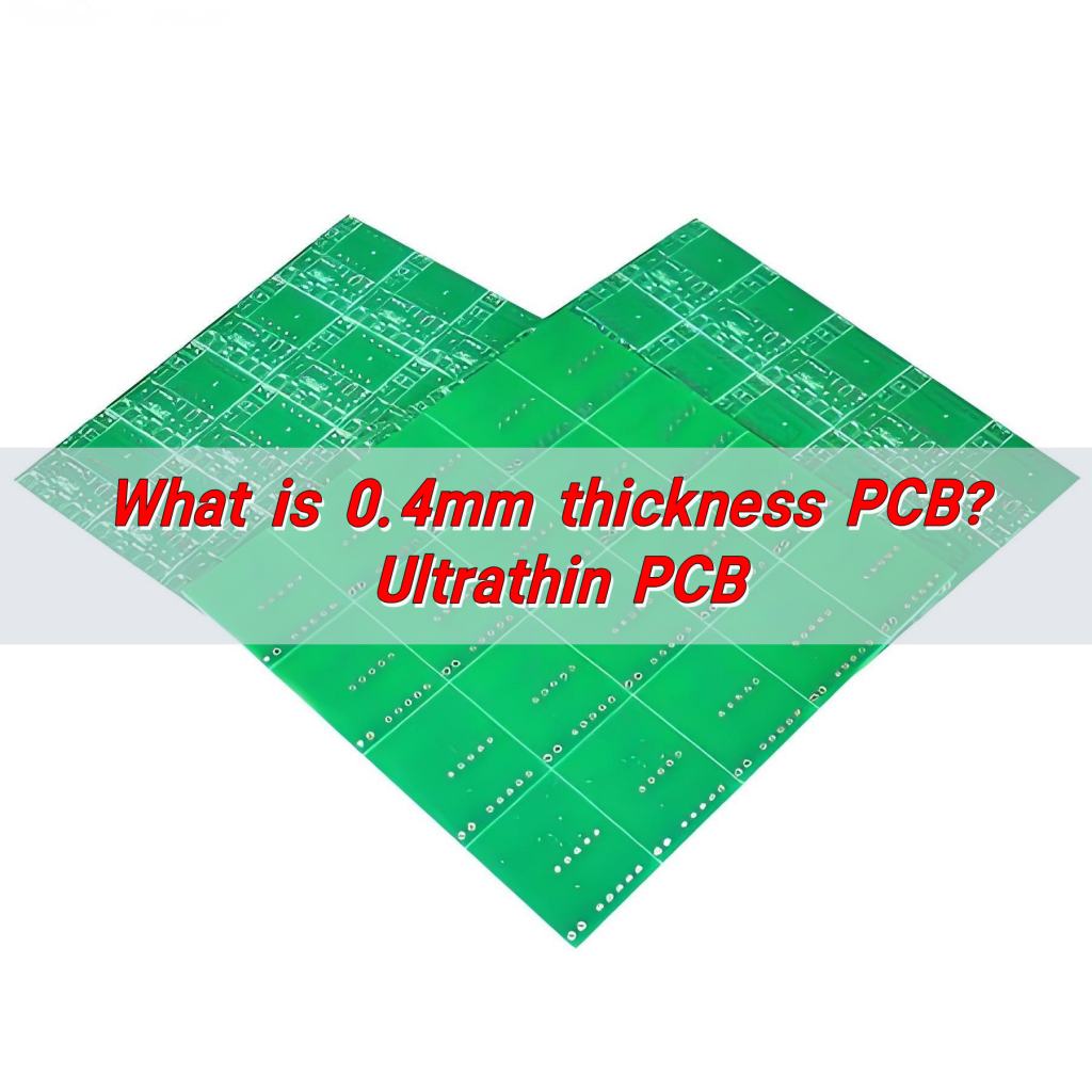
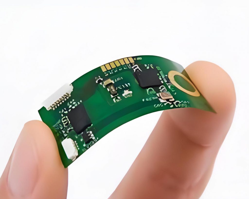
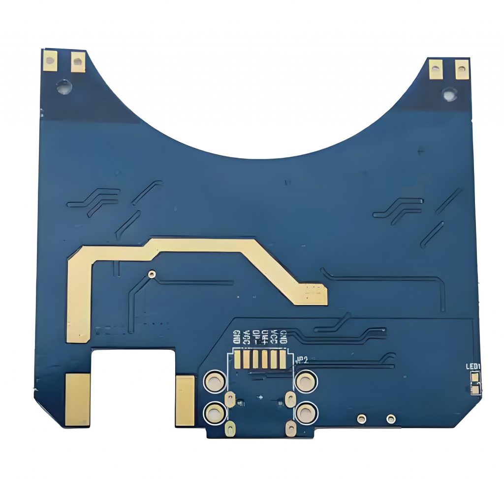
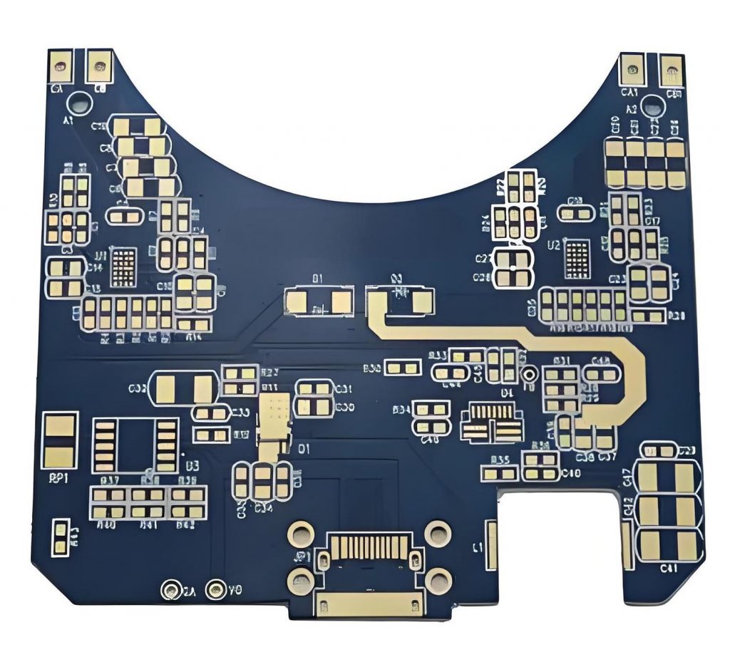
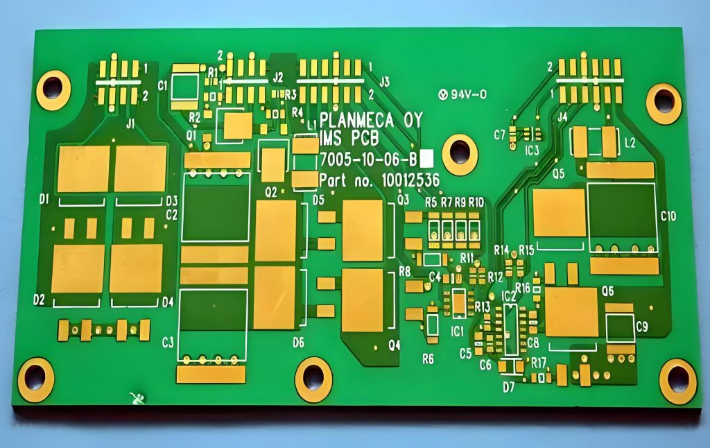
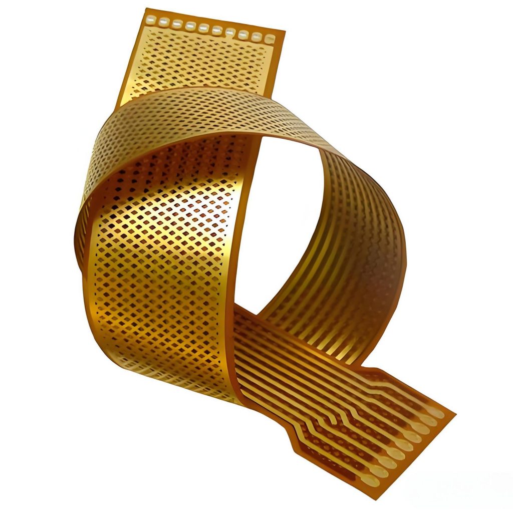
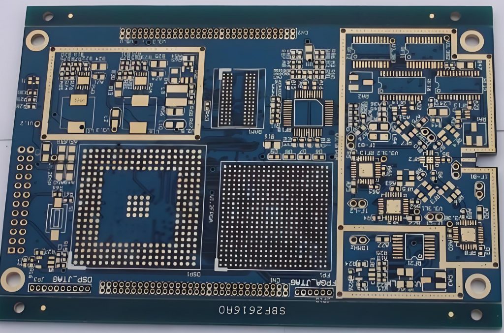
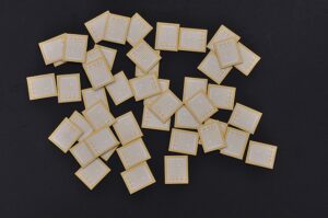
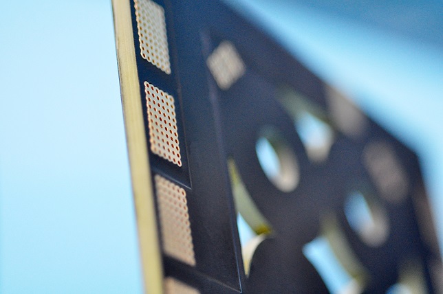
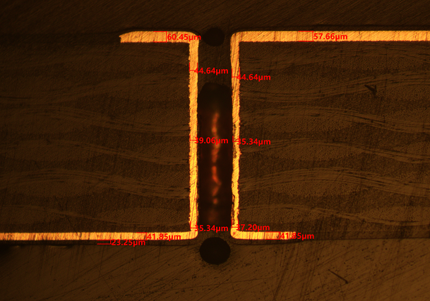
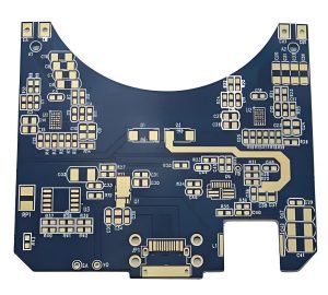
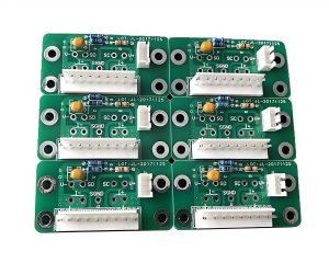
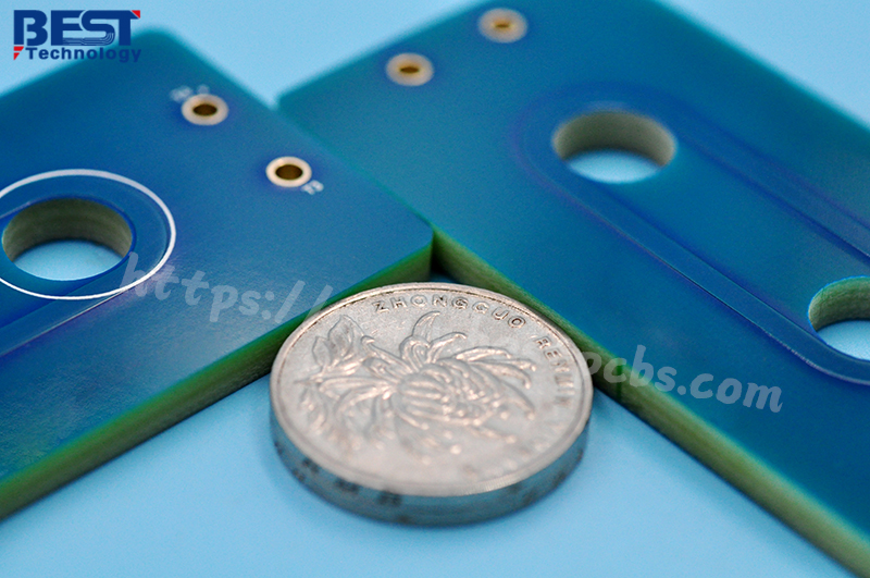
What is 0.4mm thickness PCB? 0.4mm thickness PCB is an ultra-thin printed circuit board with a thickness of only 0.4 mm. This type of PCB has high requirements in design and manufacturing, because its thinness makes it easy to cause problems such as warping and deformation during processing. 0.4mm thickness PCB is usually used in electronic devices with strict requirements on space and weight. It can meet the development trend of miniaturization and thinness of modern electronic products.

What is 0.4mm thickness PCB? Ultrathin PCB

What is a 0.4mm Thickness PCB?

A 0.4mm thickness PCB refers to a printed circuit board with a thickness of 0.4 mm. ‌This thickness of PCB is generally considered to be the minimum thickness starting point for multi-layer PCB design, suitable for application scenarios that require highly integrated and compact design‌.

0.4mm PCB has the following characteristics:

  • Thin design‌: Suitable for electronic products that require highly integrated and compact design, such as smartphones, tablets and other portable devices.
  • High reliability: Due to its thin design, 0.4mm PCB performs well in complex wiring and fine design, and can provide stable electrical performance and mechanical strength.
  • ‌Cost-effectiveness‌: Although the manufacturing process is more complicated, the overall cost is relatively low because it uses less material.

0.4mm PCB is mainly used in the following fields:

  • Portable devices: Such as smartphones, tablets, wearable devices, etc., which require lightweight and powerful circuit boards.
  • High-density interconnect applications: In occasions where high integration and complex wiring are required, 0.4mm PCB provides a better solution.
  • Radio frequency identification (RFID) and smart cards: Such as RFID tags, IC cards, SIM cards, etc., these applications require circuit boards that are both thin and reliable.

What are the advantages of 0.4mm thickness PCB?

0.4mm thickness PCB has the following advantages:

  • Reduced material cost: Due to the use of less expensive materials such as copper, the material cost of 0.4mm thickness PCB is lower.
  • Compatibility with advanced technologies: PCBs of this thickness are compatible with advanced technologies such as laser direct imaging and can be used without damaging flexible circuits.
What is 0.4mm thickness PCB? Ultrathin PCB
  • High reliability: Ultra-thin PCBs can host custom repeatable routing paths, reduce rework, and have higher reliability.
  • Strong protection: The conductors on these PCBs have a polyimide cover layer to protect against a range of potentially harsh conditions, such as vibration and acceleration on the joints.
  • High durability: 0.4mm thick PCBs can withstand millions of bending cycles and are suitable for applications that require frequent bending.

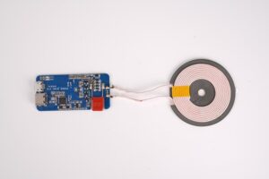
In addition, 0.4mm thick PCBs are suitable for a variety of application scenarios, including RFID smart cards, IC cards, SIM cards, electronic tags, mobile phone charging modules, wearable devices, etc.

What are the disadvantages of 0.4mm thickness PCB?

The disadvantages of 0.4mm thickness PCB mainly include the following aspects:

  • Difficulty in manufacturing: Due to the thinness of 0.4mm thickness PCBs, they are easily affected by external factors during the manufacturing process, which increases the difficulty and cost of manufacturing.
  • Lower mechanical strength: Thinner PCBs are more likely to deform or be damaged when subjected to external forces, especially in environments with high-frequency vibration or mechanical shock, which may affect their stability and reliability.
  • Poor heat dissipation: Thinner PCBs have a relatively small heat dissipation area, which is not conducive to the rapid dissipation of heat, and may cause local overtemperature, affecting the stable operation of electronic components.
  • Increased welding difficulty: During the welding process, thinner PCBs are easily affected by the welding temperature, which may cause loose welding points or welding defects.
  • Signal transmission problems: Thinner PCBs may affect the integrity and transmission speed of signals due to the shorter signal path when transmitting high-frequency signals.

How to make 0.4mm thickness PCB?

There are many aspects to consider when making 0.4mm thickness PCBs.

1. Material selection

  • Substrate: Select a substrate suitable for 0.4mm thickness. Generally, 0.3mm raw materials are used to make 0.4mm PCB boards. The type of substrate is usually FR-4 or other materials suitable for thin boards.
  • Copper foil thickness: The thickness of the copper foil affects the conductivity and strength of the PCB. Common copper foil thicknesses include 1 ounce (about 35 microns), 2 ounces (about 70 microns), etc.

2. Production process

  • Cutting: Cutting large-sized copper foil boards into small pieces suitable for production.
  • Drilling: Drilling is the first process for the formal production of circuit boards, including electrical holes, mechanical holes, vias, etc. For 0.4mm thick PCBs, laser drilling may be required to achieve smaller apertures.
  • Lamination: By combining different core thicknesses and prepreg sheets, a finished PCB thickness of 0.4mm can be achieved.
  • Electroplated: Electroplated after drilling to ensure good conductivity in the hole.
  • Solder mask: Add a solder mask to the surface of the PCB to protect the copper wire from oxidation and prevent short circuits during welding.
  • Surface treatment: Common surface treatment methods include immersion gold, tin spraying, etc. to improve the conductivity and oxidation resistance of the PCB.

What are the difficulties in making a 0.4mm thick PCB?

The main difficulties in making a 0.4mm thick PCB include the following aspects:

  • Lamination difficulties: As the copper thickness increases, the line gap is deeper, and more resin filling is required, which increases the complexity and cost of processing.
  • Drilling difficulties: As the board thickness increases, the drilling difficulty increases. Thick copper boards are usually thicker than 2.0mm, and new knives and segmented drilling techniques are required to reduce the difficulty when drilling.
  • Thermal management: Due to the increase in power consumption of electronic devices, thermal management has become a key challenge. When designing, it is necessary to consider appropriate heat dissipation structures and heat dissipation component layouts to ensure that components work properly and avoid thermal damage.
  • ‌Signal integrity‌: High-frequency signals and high-speed digital signal transmission need to consider issues such as signal loss, impedance matching, and interlayer crosstalk.
  • ‌Electromagnetic compatibility (EMC) and electromagnetic interference (EMI): Measures need to be taken to reduce electromagnetic radiation and improve anti-interference capabilities.
  • Process and material selection: Choose the appropriate printing method and substrate material to ensure that the circuit board that meets the requirements is manufactured.

How to deal with the warping problem of 0.4mm thick PCB?

There are several ways to deal with the warping problem of 0.4mm thick PCB:

  • Choose high Tg board: Boards with higher Tg can withstand higher temperatures and reduce warping caused by temperature changes. Although the cost is higher, it can effectively resist high temperature deformation.
  • Reduce via restrictions: The via design in multilayer boards should be reasonable to avoid excessive restrictions on the cold expansion and contraction of the board and reduce warping.
  • Control temperature changes: Appropriately reduce the reflow temperature or slow down the heating and cooling speed to reduce the expansion and contraction of materials caused by temperature changes.
  • Use laser drilling technology: Laser drilling can reduce stress during processing and reduce the risk of warping.
  • Mechanical leveling: Use a flattening machine to mechanically level the PCB, which is suitable for PCBs with moderate warping.

The following aspects can be used to deal with the warping problem of 0.4mm thickness PCB:

What should I pay attention to when using 0.4mm thickness PCB?

The following points should be noted when using 0.4mm thickness PCB:

  • Trace spacing and width: On 0.4mm thickness PCB, the trace spacing is usually recommended to be no less than 0.2mm to ensure stable signal transmission and reduce interference. The trace width should be designed according to the current carried. Usually the width of the power line should be between 1.2~2.5mm, and the width of the signal line should be between 0.2~0.3mm.
  • Wiring rules: In high-density and high-precision PCB design, the line width and spacing are generally set to 0.3mm. If solder mask defined (SMD) pads are used, the thickness of the traces between the pads should be appropriately reduced to avoid the problem of pad lifting during soldering or desoldering.
What is 0.4mm thickness PCB? Ultrathin PCB
  • Heat dissipation and mechanical support: For devices with high power consumption, 0.4mm thick PCBs may not be enough to provide sufficient mechanical support and heat dissipation performance. For such devices, it is recommended to choose a thicker PCB to provide better mechanical support and heat dissipation performance.
  • Design details: When designing the PCB, it should be noted that the spacing between components should be greater than 0.5mm, and the spacing between the chip pins and peripheral devices should be greater than 1.0mm. In addition, the width of the ground line should be greater than the power line to ensure a stable current supply.

0.4mm thick PCB has become an ideal choice for modern electronic products such as smartphones and wearable devices due to its ultra-thin characteristics, meeting the development needs of miniaturization and thinness. However, problems such as warping are prone to occur during production. As a professional PCB manufacturer, BEST Technology has strong manufacturing strength to ensure that each 0.4mm thick PCB effectively reduces the occurrence of warping. If you have corresponding needs, please feel free to contact us at sales@bestpcbs.com!

You may also like

How thick is 2 oz of copper on a PCB?
Friday, January 3rd, 2025

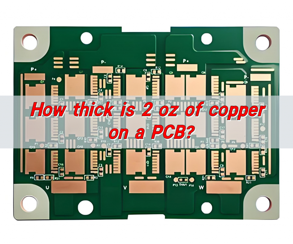
How thick is 2 oz of copper on a PCB? The thickness of 2 oz of copper on a PCB is about 70ÎŒm. Ounces are the common unit of PCB copper foil thickness. The thickness of 1 oz copper foil is generally about 35ÎŒm, so the thickness of 2 oz copper foil is about twice that of 1 oz, which is about 70ÎŒm.

How thick is the copper on a PCB board?

The copper layer thickness on a PCB board is usually between 1oz (35ÎŒm) and 4oz (140ÎŒm), while the copper layer thickness of a thick copper board can exceed this range, even reaching 10oz or more.

How thick is 2 oz of copper on a PCB?

Copper layer thickness selection in different application scenarios

  • Signal transmission: For signal transmission, a copper layer thickness of 1oz is usually sufficient, because signal transmission mainly focuses on signal integrity and stability.
  • High current applications: For applications that need to withstand high currents, such as power supplies and industrial control equipment, 2oz or higher copper layer thicknesses are more suitable because they provide better conductivity and carrying capacity.
  • Special applications: In some special applications, such as motor controllers and battery management systems for new energy vehicles, the high performance of thick copper boards can meet their stringent requirements.

What is the standard thickness of the copper layer on a PCB?

The standard thickness of the copper layer on a PCB usually ranges from 1oz to 4oz. The specific choice depends on the application scenario and requirements. For signal transmission, a thickness of 1oz is usually sufficient; for occasions that require high current, 2oz or 3oz copper thickness is more suitable.

Application scenarios of copper layers of different thicknesses

  • 1oz copper thickness: suitable for general signal transmission, such as ordinary double-sided boards.
  • 2oz copper thickness: suitable for occasions that require larger currents, such as power boards.
  • 3oz copper thickness: suitable for high current and high power applications, such as some special industrial equipment.

The choice of copper layer thickness is mainly based on the purpose of the circuit board, the signal voltage and the current. In addition, thicker copper layers can improve the electrical performance and load-bearing capacity of the circuit board, but it will also increase the manufacturing cost.

How to calculate PCB thickness?

The calculation of PCB thickness mainly depends on the thickness of the copper foil and the number of layers and structure of the PCB.

The thickness of the copper foil is usually expressed in ounces (OZ), and 1OZ copper foil is approximately equal to 35 microns (um) or 1.4 mils (mil). Common PCB copper foil thicknesses are 17.5um, 35um, 70um, etc.

How thick is 2 oz of copper on a PCB?

The thickness of the multilayer board also needs to consider the lamination loss, which is usually related to the residual copper rate of the inner copper foil. The specific formula for calculating the lamination thickness is: Lamination thickness = PP theoretical thickness – lamination loss.

What is the difference between 1oz and 2oz copper PCB?

The main difference between 1oz and 2oz copper PCBs is the thickness of the copper foil and the applicable scenarios.

1. Copper foil thickness:

  • 1oz copper thickness: 1oz copper thickness means that the weight of copper foil per square foot of board area is 1 ounce (about 35.3 grams), and the corresponding copper foil thickness is about 1.4 mils (0.035mm).
  • 2oz copper thickness: 2oz copper thickness means that the weight of copper foil per square foot of board area is 2 ounces (about 70.6 grams), and the corresponding copper foil thickness is about 2.8 mils (0.071mm).

2. Applicable scenarios:

  • 1oz copper thickness: Suitable for most common circuit board designs and applications because it is low cost and can meet general needs.
  • 2oz copper thickness: Suitable for applications that require higher current carrying capacity, such as power electronic devices and high-power LEDs.

3. Cost:

  • 1oz copper thickness: It is a common choice due to its low cost.
  • 2oz copper thickness: Due to the thicker copper foil, the cost is relatively high.

How thick is the copper in a flex PCB?

The copper thickness in a flexible PCB is usually 1/3 ounce (OZ), 1/2OZ, 1OZ and 2OZ, and the corresponding physical thickness is 12ÎŒm, 18ÎŒm, 35ÎŒm and 70ÎŒm respectively.

How thick is 2 oz of copper on a PCB?

Choosing the right copper thickness is a key link in the design of flexible boards, and factors such as the application requirements, cost and technical feasibility of the circuit board need to be considered. Thicker copper foil can provide better current conduction, reduce resistance and heat generation, and improve the stability and efficiency of the circuit, but at the same time it will increase the cost and processing difficulty.

What is the thickness tolerance of copper in PCB?

The thickness tolerance standard of copper in PCB mainly depends on the type and specification of the board used.

According to the GB/T 4722 standard, the common PCB board copper thickness standard tolerances are as follows:

  • 0.5mm board thickness: coarse tolerance is ±0.07mm, fine tolerance is ±0.01mm.
  • 0.7mm board thickness: coarse tolerance is ±0.15mm, fine tolerance is ±0.09mm.
  • 0.8mm plate thickness: rough tolerance is ±0.15mm, fine tolerance is ±0.09mm.
  • 1.0mm plate thickness: rough tolerance is ±0.17mm, fine tolerance is ±0.11mm.
  • 1.2mm plate thickness: rough tolerance is ±0.18mm, fine tolerance is ±0.12mm.
  • 1.5mm plate thickness: rough tolerance is ±0.20mm, fine tolerance is ±0.14mm.
  • 1.6mm plate thickness: rough tolerance is ±0.20mm, fine tolerance is ±0.14mm.
  • 2.0mm plate thickness: rough tolerance is ±0.23mm, fine tolerance is ±0.15mm.
  • 2.4mm plate thickness: rough tolerance is ±0.25mm, fine tolerance is ±0.18mm.
  • 3.2mm board thickness: the rough tolerance is ±0.30mm, and the fine tolerance is ±0.20mm.

In addition, according to the IPC-6011 standard, the inner layer copper thickness tolerance is usually 10%, and the outer layer copper thickness tolerance is usually +20%. For PCBs with a thickness of less than 1mm, the board thickness tolerance is ±10% of the board thickness; for PCBs with a thickness greater than or equal to 1mm, the board thickness tolerance is ±0.10%.

How to choose PCB copper layer thickness?

There are several key factors to consider when choosing the thickness of the PCB copper layer:

  • Current carrying capacity: Generally speaking, the thicker the copper, the better the electrical performance of the circuit board, and it can carry more current. For power lines or high-power applications that require large currents to pass through, using thicker copper foil can effectively reduce the temperature rise of the line and avoid performance degradation or safety issues caused by overheating.
How thick is 2 oz of copper on a PCB?
  • Signal transmission quality: Thicker copper foil can reduce wire resistance, reduce attenuation and delay during signal transmission, and thus improve signal integrity. Especially in high-frequency circuit design, precise control of copper foil thickness is the key to achieving good impedance matching, reducing signal reflection and crosstalk.
  • Cost considerations: The thicker the copper, the higher the cost of the circuit board. Because thicker copper foil will increase material costs and processing difficulty, leading to an increase in overall costs.

Application scenarios Ordinary double-sided boards usually use 1oz copper thickness, while the inner layer of multi-layer boards is generally 1/2oz or 1/3oz, and the outer layer is 1oz or 1/2oz1. For circuits that require high current, 2oz or 3oz copper thickness may be used.

In short, the PCB copper thickness varies greatly. 0.5 ounce copper foil is low in cost and easy to process, suitable for simple and small products; 1 ounce is highly versatile and suitable for general electronic products; 2 ounces of copper is about 70ÎŒm thick, can carry more current, and has relatively good heat dissipation performance, but it is costly and difficult to process, and is often used in industrial equipment with extremely high power requirements. The copper thickness should be selected according to the actual situation of product function, cost, etc. to ensure that it is easy to use and economical.

You may also like

What are printed circuit board thickness standards?
Monday, September 23rd, 2024

What is the Standard Thickness of a PCB?

The standard thickness of a PCB is often 1.6 mm. This has become the go-to thickness in the industry because it balances flexibility, cost, and performance for most applications. However, depending on the requirements of the design, PCB thickness can vary widely.

What are printed circuit board thickness standards?

Manufacturers offer various thicknesses to accommodate specific designs, from 0.4 mm (0.016 inches) for ultra-thin, flexible boards, up to 3.2 mm or even thicker for high-current, rugged applications. The choice of thickness largely depends on the type of application and the mechanical strength needed.

How is PCB Thickness Measured?

Measuring PCB thickness accurately is crucial for ensuring the board meets design specifications and performs optimally in its application. The thickness of a PCB refers to the total height of the board, including all its layers—copper, dielectric, and solder mask. This thickness plays a role in many factors, from electrical performance to mechanical stability, and must be precisely controlled. The tools and methods used to measure PCB thickness include:

1. Micrometers

    A micrometer is the most common tool for measuring PCB thickness. It allows precise measurements down to fractions of a millimeter, making it ideal for multilayer PCBs where small deviations can affect performance. The micrometer is placed at various points across the board to ensure uniform thickness.

    2. Calipers

    Digital or analog calipers are also used to measure the thickness of PCBs. They are particularly useful for quickly gauging thickness across different sections of the board.

    3. Cross-Sectioning

    In cases where even more precision is required, manufacturers may opt to cross-section the board. This involves cutting a sample of the PCB and measuring it under a microscope to analyze each layer’s contribution to the overall thickness.

    What are printed circuit board thickness standards?

    PCB thickness is typically measured in mils (1 mil = 0.001 inches) or millimeters, depending on the region and industry. Standard PCB thicknesses usually fall between 0.4 mm (0.016 inches) and 3.2 mm (0.125 inches), but custom designs may require other dimensions.

    In mass production, quality control procedures are in place to ensure that the boards maintain a consistent thickness across large batches. Thickness tolerances range from ±10% to ±20%, depending on the manufacturer and materials used.

    How Thick is a 2-Layer PCB Board?

    A standard 2-layer PCB is typically 1.6 mm thick, but this can vary based on specific requirements. The board consists of two copper layers, one on each side of the insulating core.

    Core Thickness: The thickness of the insulating material between the two copper layers is generally around 1.4 mm.

    Copper Thickness: Standard copper thickness is 35 ÎŒm (1 oz copper), though this can be adjusted for higher current-carrying capacity.

    What are printed circuit board thickness standards?

    For lighter applications, such as compact consumer electronics, a thinner board of 0.8 mm may be used, providing more flexibility and space-saving. Meanwhile, more robust applications may demand thicknesses exceeding 2.4 mm.

    How Thick is a Standard 8-Layer PCB?

    When it comes to multilayer PCBs like the 8-layer variant, thicknesses usually range from 1.4 mm to 2.4 mm, depending on the design requirements. With multiple layers of copper and insulating material stacked together, manufacturers must optimize thickness while considering electrical performance and mechanical rigidity.

    Each additional layer introduces more copper and insulation, increasing the overall thickness. For high-frequency applications or boards that must handle significant current, thicker boards may be necessary to ensure signal integrity and thermal management.

    How Does PCB Thickness Affect Thermal Performance?

    The influence of PCB thickness on thermal performance is mainly reflected in heat dissipation efficiency and heat capacity.

    The thickness of the PCB directly affects its heat dissipation efficiency. Thicker PCBs have greater heat capacity and better heat conductivity, and are able to conduct the heat generated by electronic components more effectively. This is because copper has good thermal conductivity, and the thicker copper foil layer can more quickly transfer heat from the heating element to the cooling area or external radiator, helping to improve the overall thermal management efficiency and protect sensitive components from thermal damage.

    In addition, the thickness of the PCB is also closely related to its mechanical strength and stiffness. Thicker PCB boards have higher flexural stiffness and impact toughness, can withstand greater mechanical stress and vibration, and ensure the stability and reliability of electronic equipment in harsh environments. This is equally important in thermal management, as it helps to maintain the stable operation of electronic equipment in high temperature environments and prevent performance degradation or damage due to overheating.

    However, it is important to note that while thicker PCBs are good for heat dissipation, in high-frequency applications, excessively thick PCBs may increase the impedance and coupling of the signal, thus affecting electrical performance.

    What Factors Influence PCB Thickness?

    PCB board thickness is one of the key parameters to be considered in the design process, which has a great impact on the performance and reliability of the circuit board. When choosing plate thickness, the following factors need to be considered:

    1. Signal speed

    The thinner the plate, the faster the signal speed, and vice versa. However, when the board thickness is less than 0.8mm, the signal will have a great loss, will produce serious signal interference, affecting the normal work of the circuit board.

    2. Heat conduction

    The thinner the board thickness, the worse the heat dissipation ability, easy to produce hot spots and thermal runaway phenomenon, affecting the performance and reliability of the circuit board.

    3. Mechanical strength

    The greater the thickness of the plate, the higher the mechanical strength, the smoother the surface of the plate, and the greater the bending strength. However, too thick a board will affect the assembly and size of the board design.

    4. Number of layers

    More layers mean a thicker board. A single-layer PCB may be as thin as 0.4 mm, while multilayer boards like an 8-layer PCB may reach over 2 mm.

    Taking the above factors into consideration, it is usually appropriate to choose the plate thickness between 1.6mm-2.0mm.

    How to Decide PCB Thickness?

    According to different applications and needs, PCB board can be divided into a variety of thicknesses, commonly used board thickness is 0.8mm, 1.0mm, 1.2mm, 1.6mm, 2.0mm and so on. When selecting PCB board thickness, it is necessary to make comprehensive consideration according to specific application scenarios and design requirements. Here are a few ways to choose plate thickness:

    1. Determine according to the circuit complexity and working environment

    When the circuit complexity is high, multiple components need to be connected at the same time, or the circuit board needs to work in a high temperature environment, you are advised to select a thicker board thickness to effectively improve the performance and reliability of the circuit board.

    2. Determine the device size and type

    If the device size is small and requires precision assembly, a thinner plate thickness is recommended. For large devices, such as power switches and high-power LED lights, it is recommended to choose a thicker board thickness.

    3. Determined according to design requirements and cost control

    In terms of cost control, the thinner the plate thickness, the higher the corresponding plate cost will be. Therefore, the cost and performance should be considered comprehensively in the design, and the most appropriate plate thickness should be selected.

    In addition, as an 18+ years experienced PCB manufacturer, we summarized a small tip for choosing PCB thickness, hope this is help for you.

    • The board thickness below 1.0mm is generally used for small electronic devices and mobile devices, such as smart watches, Bluetooth headsets and so on.
    • 1.0mm-1.6mm PCB thickness is suitable for most common electronic devices, such as smart phones, tablets, digital cameras, etc.
    • Thickness >1.6mm is generally used for industrial control equipment, power switches and other large electronic equipment.

    Advanced PCB Manufacturer – Best Technology

    At Best Technology, we specialize in manufacturing high-quality PCBs tailored to meet your exact design specifications. We offer custom thickness options for single-layer, double-layer, and multilayer boards.

    We understand that PCB thickness is critical to performance, whether you’re working on high-current applications or compact designs. Our team of experts can guide you through the selection process, ensuring that your boards are not only optimized for electrical performance but also for thermal and mechanical stability.

    You may also like

    1.2mm vs 1.6mm PCB: What PCB Thickness to Choose?
    Monday, September 9th, 2024

    When designing or selecting a PCB board, thickness is a key consideration. The most common thicknesses are 1.2mm and 1.6mm PCB, but which one is right for you? Each has its advantages depending on the application. Whether you’re designing for compact devices, high-power applications, or something in between, choosing the right PCB thickness will impact performance, cost, and durability.

    In this blog, we’ll compare the two most popular thicknesses—1.2mm and 1.6mm—and explore their key differences. We’ll help you understand why most PCBs are 1.6mm thick, when to consider 1.2mm PCBs, and what factors to keep in mind during your decision-making process.

    1.2mm vs 1.6mm PCB: What PCB Thickness to Choose?

    Why are PCBs 1.6mm Thick?

    The 1.6mm thickness has become the standard for most PCBs. But why is this the preferred thickness? One reason is historical—it was a size that worked well for manufacturing processes when PCBs were first developed. Over time, this became the norm due to its balance between durability and flexibility.

    From the perspective of process and cost, the thinner the PCB board, the higher the manufacturing cost. Because it is necessary to use higher levels of materials and more refined processes to meet the various requirements of PCB boards in the manufacturing process. At the same time, PCB boards that are too thin are also susceptible to environmental and mechanical forces and have poor stability. Therefore, under the premise of taking into account cost and stability, 1.6mm has become a more common PCB board thickness.

    Secondly, from the perspective of compatibility and standardization, in the vacuum tube era, because the development and manufacturing of PCB substrates have not yet achieved industrial production, PCB board thickness is mainly determined according to the equipment housing/installation hardware or the required PCB board thickness. At that time, the 1.6mm specification gradually became the industry standard and provided compatibility and convenience for later PCB manufacturing and design.

    In addition to 1.6mm, there are some other common PCB board thickness, such as 0.8mm, 1.0mm, 1.2mm, 2.0mm and so on. These thicknesses are usually selected based on specific application and design requirements.

    For example, in the field of communications, the commonly used PCB board thickness is generally 0.8mm; In the field of consumer electronics, the commonly used PCB board thickness is generally 1.0mm. In addition, for some specific applications, you can also choose other non-standard thickness options, such as 0.4mm, 0.6mm, 2.4mm, etc.

    How Thick is a 1.2mm PCB?

    Compared to the standard 1.6mm, a 1.2mm PCB is thinner, which makes it ideal for compact designs where space is at a premium. The 1.2mm thickness reduces the overall weight of the PCB, which can be critical in devices like smartphones, wearables, and other portable gadgets.

    Despite being thinner, 1.2mm PCBs can still provide good mechanical support and electrical performance, though they might not be as resistant to bending or mechanical stress as their thicker counterparts. This makes them better suited for applications that do not require heavy-duty handling or exposure to harsh environments.

    1.2mm vs. 1.6mm PCB

    So, how do you decide between a 1.2mm and a 1.6mm PCB? It depends on the specific needs of your project. Here are some factors to consider:

    • Mechanical Strength

    A 1.6mm PCB is more rigid and can withstand greater mechanical stress, making it ideal for larger devices or environments where the board may face pressure or force. If your design requires a sturdy board, 1.6mm is a better option.

    • Compact Design

    For smaller, more compact devices, a 1.2mm PCB can save valuable space and reduce the overall profile. This is especially important for handheld gadgets or portable electronics where size and weight matter.

    • Thermal Management

    Thicker boards like the 1.6mm version have better thermal management properties, as they can dissipate heat more efficiently. If your PCB will handle high power or generate a lot of heat, the 1.6mm option may be a better fit.

    • Cost

    While the difference in cost between 1.2mm and 1.6mm PCBs is usually minimal, thinner boards might be slightly more cost-effective, especially for large-volume production. However, always weigh this against the performance needs of your application.

    Ultimately, the decision comes down to the balance between durability, size, and the operating environment of your product.

    Is Thinner PCB Better?

    A thinner PCB, like the 1.2mm version, can be better in certain applications, but it’s not universally superior. The key benefit is the reduced thickness, which translates to lighter and more compact products. This is why thinner PCBs are favored in modern consumer electronics where every millimeter counts.

    However, thinner PCBs are less rigid, making them more prone to bending or warping under pressure. If the PCB is subjected to mechanical stress or has to endure rough handling, a 1.6mm thickness might be the safer choice.

    For low-stress applications, such as small gadgets or tightly packed devices, a 1.2mm PCB can offer the perfect balance of performance and size. The goal is to match the thickness to the demands of your specific project.

    What is the Tolerance of a 1.6mm PCB?

    PCB manufacturers often specify tolerances to account for minor variations in thickness during production. For a 1.6mm PCB, the typical tolerance range is around ±0.10mm, though this can vary based on the manufacturer and specific requirements of the project.

    Tolerances are crucial in ensuring that the PCB fits within the required mechanical constraints of the final product. When designing a product, it’s essential to account for this tolerance, especially if your design requires exact thickness dimensions.

    The tolerance of a 1.6mm PCB helps ensure consistent performance, even with minor deviations in the manufacturing process.

    How Thick is a Standard 2-Layer PCB?

    A standard 2-layer PCB typically ranges from 1.6mm to 2.4mm in thickness. However, 1.6mm is the most common thickness for 2-layer boards used in a wide range of applications.

    The two layers refer to the copper traces that are used for electrical connections, and the thickness of the board itself determines its strength, thermal properties, and overall performance. In most cases, a 1.6mm thickness offers an ideal balance for general use, providing both durability and flexibility in terms of design and assembly.

    How to Choose a Suitable PCB Thickness?

    When choosing the thickness of a PCB, several factors need to be considered:

    1. Weight

    Weight is a key factor. Thinner boards tend to be more fragile and are more likely to break. Therefore, if lightweight is not a strict requirement, thicker boards are usually the better choice.

    2. Flexibility

    Flexibility is another important consideration. Thinner boards are generally more flexible, but they are also more prone to breaking. Thicker boards offer less flexibility but provide greater stability.

    3. Space

    The amount of space available in your device is crucial when deciding on PCB thickness. If your device has enough room to accommodate a thicker PCB, then using a thicker board is advisable. On the other hand, if the device is compact, a thinner PCB may be necessary to fit into the available space.

    4. Type of Connectors and Components

    The type of connectors and components you plan to use also influences the PCB thickness. Different components may have specific requirements that determine the board’s thickness.

    5. Dimensions and Design

    When selecting PCB thickness, factors such as the dimensions of the PCB, the number of layers, the weight of the installed components, the installation method, and impedance should all be considered. A general rule of thumb is: when the aspect ratio of the PCB (length to width) is not greater than 2 and the width-to-thickness ratio is not greater than 150, the performance is optimal. The width here refers to the smaller dimension between the depth or height of the PCB.

    For plug-in boards mounted in vertical boxes, the thickness should fully consider deformation issues. For PCBs that are not box-mounted, if the size is smaller than 300mm x 250mm, 1.6mm to 2mm thick boards are preferred. Larger PCBs should use 2mm, 2.4mm, 3mm, 3.2mm, 3.5mm, or even thicker boards, but it is best to avoid exceeding 4mm.

    6. Copper Thickness, Layers, and Signal Type

    When determining the PCB thickness, you should also factor in the copper thickness, the material of the board, the number of PCB layers, the types of signals it will carry, and the type of through-holes being used. The operating environment is another key consideration.

    PCB Manufacturing Considerations

    Several manufacturing factors also influence the final PCB thickness:

    • Drilling equipment capability
    • Copper thickness
    • Number of layers
    • Board cutting method

    For non-standard thickness PCB designs, additional factors include:

    1. Manufacturer Capability

    The first consideration is whether your PCB manufacturer has the equipment and capability to produce the specific thickness you need. This decision should be made early in the design process, along with other Design for Manufacturing (DFM) requirements. Otherwise, you may need to make changes and redesign your PCB stack-up.

    2. Extended Delivery Time

    If your manufacturer does not stock the materials required for non-standard thickness, it could delay the production timeline. Therefore, it’s essential to consider the delivery time when choosing a non-standard thickness.

    3. Additional Costs

    This is perhaps the most important point: you need to evaluate the cost of special materials, additional manufacturing costs, and the potential impact of delayed delivery to determine if the extra expenses are justifiable.

    Opting for standard PCB thicknesses typically results in faster production and lower costs. However, if you decide on a non-standard thickness, it’s crucial to communicate with your manufacturer early in the design phase. This ensures that they can meet your requirements, and you’ll also need to clarify lead times and any additional manufacturing costs.

    FAQs

    Q1: Can I customize the thickness of my PCB?

    Yes, many manufacturers offer custom thickness options ranging from thinner boards like 0.8mm to thicker boards over 2.4mm, depending on your needs.

    Q2: What are the benefits of a 1.2mm PCB?

    A 1.2mm PCB offers space-saving advantages, making it ideal for compact devices like smartphones and wearables. It also tends to be lighter.

    Q3: Will a 1.2mm PCB be more flexible?

    Yes, thinner PCBs are more flexible, which may be useful in specific applications where slight bending is acceptable.

    Q4: Why is thermal management important in PCB design?

    Proper thermal management prevents overheating and ensures the long-term reliability of the PCB, especially in high-power applications.

    Q5: What is the standard thickness tolerance for a PCB?

    The standard tolerance is usually around ±0.10mm, but this can vary depending on the manufacturer and board specifications.

    You may also like