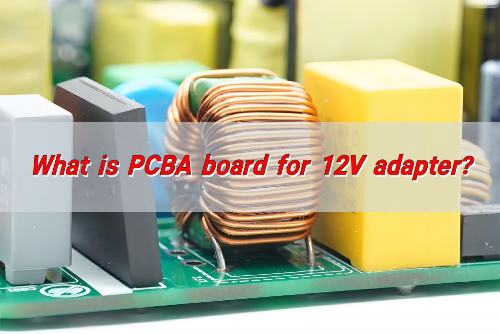
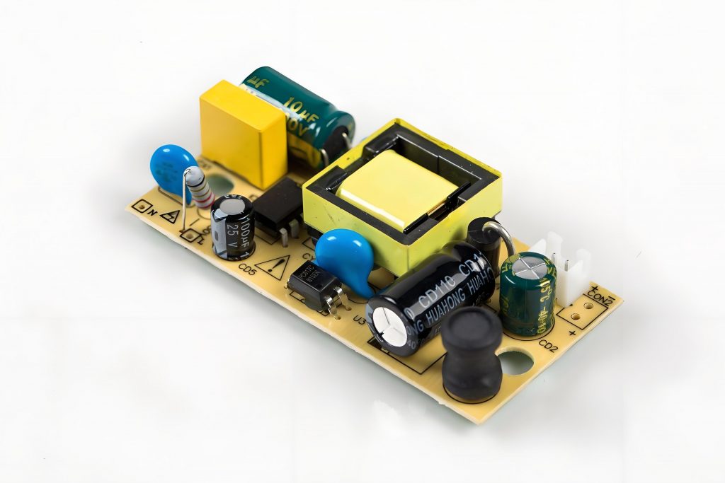
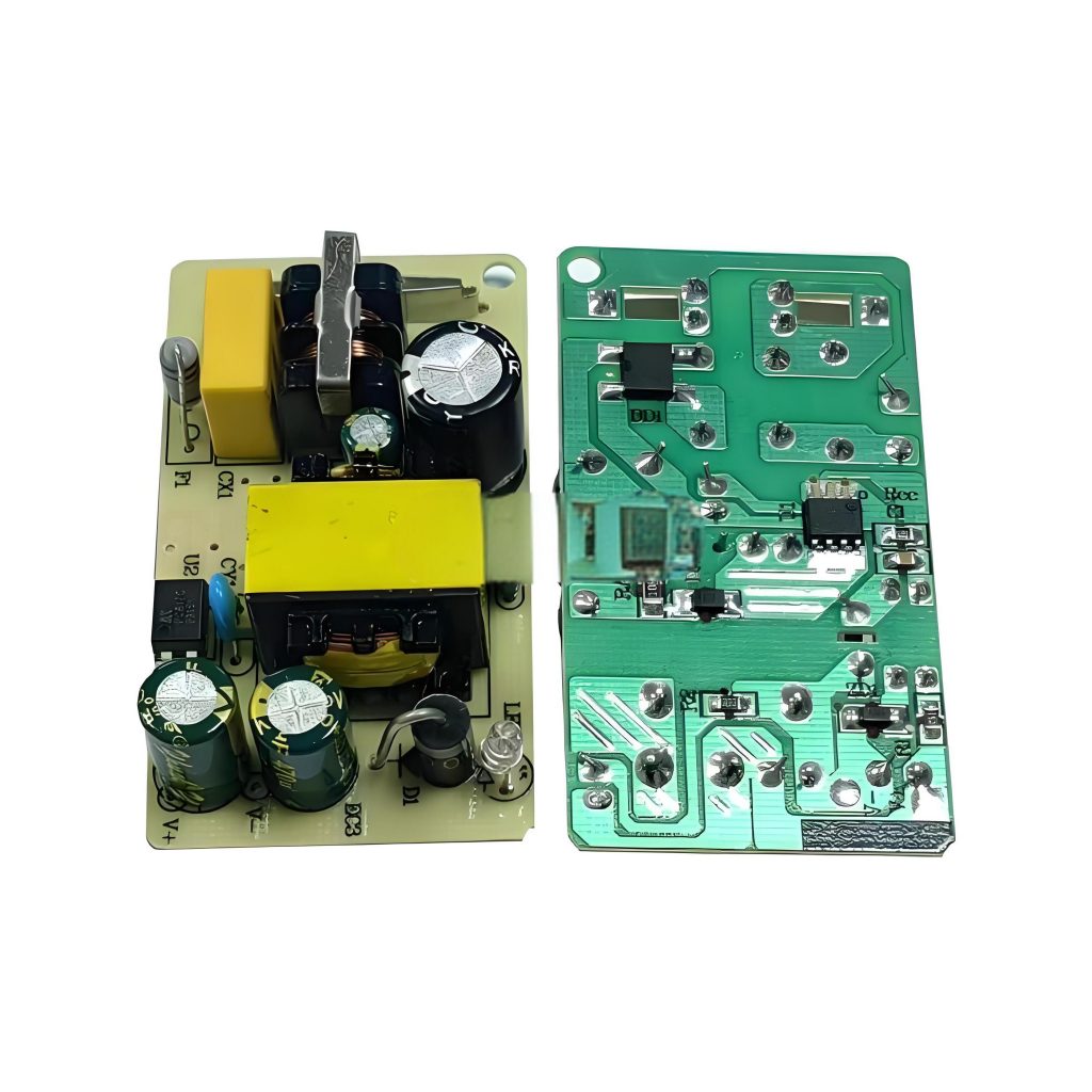
What is PCBA Board for 12V Adapter? The PCBA board of the 12V adapter is a circuit board assembly product that converts 220V AC power into 12V DC power. It is composed of PCB and various electronic components, including input terminals, transformers, rectifier bridges, filter capacitors, voltage regulator modules, output terminals, feedback circuits, and protection circuits. These components are connected to the PCB through solder to achieve stable voltage output and multiple protection functions.
What is a Power Supply PCBï¼
A power supply PCB is the heart of any electronic power system. It is the printed circuit board that manages the conversion of electrical energy from one form to anotherâusually from AC (Alternating Current) to DC (Direct Current). These boards are designed to handle specific power requirements, ensuring that voltage and current are regulated correctly for the devices they power.
For instance, a typical 12V adapter is designed to convert the electrical supply from a wall outlet (usually 110V or 220V AC) into a stable 12V DC that can safely power electronics such as routers, chargers, and small appliances. The power supply PCB in this adapter ensures the right voltage and current flow to the device, protecting both the adapter and the device being powered.
How to Design a Power PCB?
Designing a power PCB for an adapter, especially a 12V model, involves several considerations to ensure efficiency, safety, and durability.
- Component layout: put related components together to reduce the length and interference of high-impedance lines; small signal lines are kept away from large current lines; heating components are kept away from temperature-sensitive components; the layout of adjustable components takes into account the requirements of the overall structure.
- Unit circuit layout: arrange the positions of functional circuit units according to the circuit flow to ensure smooth signal flow; layout with core components as the center, and arrange components evenly, neatly and compactly; high-frequency circuits consider the distribution parameters of components, and general circuits arrange components in parallel.
- Avoid interference: avoid adjacent parallel input and output wires, and add ground wires between wires to prevent feedback coupling.
- Line width selection: determine the line width according to the current size, such as 50μm thick copper foil, 1mm wide can flow 1A current, and the temperature rise does not exceed 3â; 2 ounces thick copper foil, 1mm wide can flow 1.5A current, and the temperature rise does not exceed 3â.
- Electrical clearance: The electrical clearance width between small current lines and output lines is generally 0.75mm – 1.0mm (minimum 0.3mm).
- Cornering treatment: The routing corners are arc-shaped, avoiding right angles and sharp angles to avoid affecting the electrical performance of high-frequency circuits.
- Power line treatment: According to the current size, the width of the power line is thickened to reduce the loop impedance, so that the direction of the power line and the ground line is consistent with the data transmission direction, the surrounding area is reduced, and the anti-noise ability is enhanced.
What is a PCB Adapter?
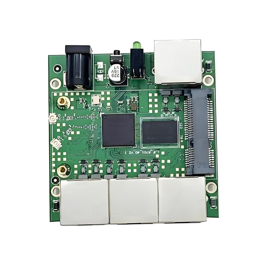
A PCB adapter refers to a circuit board that adapts one type of connection or interface to another. It is a crucial part of many electronic devices, especially when different voltage levels or types of connectors are involved.
In the context of a 12V adapter, the PCB serves as the central unit that converts the AC input (usually from the power outlet) into a regulated 12V DC output. This adapter PCB ensures that the power supplied to the device is stable and reliable, ensuring optimal performance.
What Does the PCBA Board for 12V Adapter Consist Of?
A typical PCBA board for a 12V adapter consists of several essential components. These components work together to ensure that the adapter provides stable, efficient, and safe power to connected devices. Here are the key elements:
- Input Stage: This is where the AC voltage from the wall socket enters the adapter. It typically consists of a rectifier, which converts AC to DC. The rectifier often includes diodes that allow current to flow in only one direction, effectively converting the incoming AC into pulsed DC.
- Filter Capacitors: After rectification, the DC signal can be uneven. To smooth out the waveform and make it stable, capacitors are used. These filter capacitors remove high-frequency noise and provide a smooth, steady DC voltage.
- Voltage Regulator: A crucial component of the 12V adapter, the voltage regulator ensures that the output voltage remains constant at 12V, regardless of fluctuations in input voltage or changes in load. Linear regulators or switch-mode regulators may be used, depending on the efficiency required.
- Inductors: Inductors help manage power flow by storing energy in a magnetic field. They play a role in smoothing the current flow and filtering high-frequency noise.
- Output Stage: After the voltage is regulated, it passes through an output stage that provides the final output voltage. This stage may include protection features such as over-voltage and over-current protection to prevent damage to the adapter or the device it’s powering.
- Heat Sink: To manage heat generated by the power conversion process, heat sinks are often attached to components that generate significant heat, such as voltage regulators. This helps to maintain safe operating temperatures.
- Protection Circuits: To protect the adapter and the connected devices, protection circuits are included. These may consist of fuses, over-voltage, and over-current protection, ensuring the adapter doesn’t cause damage in case of electrical faults.
How to Manufacture PCBA Board for 12V Adapter?
Manufacturing a PCBA board for a 12V adapter is a multi-step process that requires precision and attention to detail. Hereâs how it typically works:
- Design and Prototyping: The first step is designing the PCB layout and schematic. This prototype is tested to ensure that the design works as expected.
- PCB Fabrication: After finalizing the prototype, the design moves to the PCB fabrication stage. Here, the PCB material (usually fiberglass or epoxy resin) is used to create the physical board. The copper layers are etched to form the required circuit paths.
- Component Sourcing: The next step is sourcing the components, including resistors, capacitors, voltage regulators, and diodes. Components are carefully chosen based on their specifications and compatibility with the design.
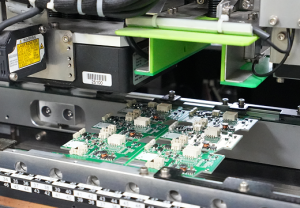
- Soldering and Assembly: Once the components are sourced, they are placed on the PCB and soldered. This can be done manually or using automated machines in a process known as Surface Mount Technology (SMT).
- Inspection and Testing: After assembly, the PCBA undergoes thorough testing to ensure it meets the required standards. This includes checking for shorts, open circuits, voltage stability, and functionality. Any defects are identified and corrected.
- Final Assembly and Packaging: Once the PCBA passes all tests, itâs assembled into the final product. For a 12V adapter, this could mean placing the board into a casing and adding the necessary connectors for the input and output. The product is then packaged and ready for shipment.
How to Give Power Supply to PCB?
Providing power to a PCB is a straightforward process, but it requires care to ensure that the right voltage and current are supplied. Here’s how you typically provide power to a PCB:
- Power Input: The power source, such as a wall outlet or battery, is connected to the PCB through the input pins. For a 12V adapter, the input will usually come from a 110V or 220V AC source.
- Voltage Conversion: The power supply on the PCB will convert the incoming AC to DC and regulate it to the required 12V. This ensures that the PCB receives the correct power for its operation.
- Connection to the Circuit: Once the power is converted and stabilized, it’s distributed to the various components of the PCB that need it, such as microcontrollers, sensors, or other parts of the electronic system.
- Monitoring: The voltage and current should be monitored to ensure that the power supply is stable and within the required range. If any issues arise, protection circuits will activate to prevent damage.
How to Connect a PCB Board?
Connecting a PCB board to the rest of an electronic system is an essential part of the design process. Here’s a simplified guide:
- Input Connections: The PCB will have input pins for power (such as 12V) and any other required signals. These are typically connected using wires or connectors to the power source or other components.
- Output Connections: Similarly, the PCB will have output pins for delivering power or signals to other devices. For example, a 12V adapter PCB will have output pins that deliver the 12V DC to the device itâs powering.
- Grounding: A proper ground connection is crucial for stable operation. The ground from the power source should be connected to the ground plane of the PCB. This ensures that the circuit is properly referenced and reduces the risk of noise or interference.
- Connector Choices: Depending on the application, different types of connectors can be used. For example, screw terminals, pin headers, or USB connectors might be used to make these connections, depending on the adapterâs design.
How Do You Connect a Power Supply to a Board?
Connecting a power supply to a PCB board is a key step in ensuring that your device works correctly. Hereâs how you can do it:
- Identify the Power Inputs: The PCB will have designated pins or pads for power input. These must be connected to the output terminals of your power supply. In the case of a 12V adapter, these inputs will typically be labeled as 12V or Vcc.
- Ensure Proper Polarity: Always ensure that the power supplyâs positive and negative terminals are connected to the correct pins on the PCB. Incorrect polarity can lead to circuit failure or damage.
- Secure the Connections: Use connectors or solder the wires to ensure a reliable, stable connection. Loose connections can cause intermittent power issues.
- Test for Stability: Once connected, itâs important to check the output voltage using a multimeter to ensure that the voltage is stable and within the expected range.
Conclusionï¼
The 12V adapter’s PCBA board is a critical component in the electronics power ecosystem. By ensuring the PCB is well designed, connections are made correctly, and power is managed efficiently, you can ensure the 12V adapter operates safely and efficiently. BEST Technology specializes in designing different types of PCBs. If you have any PCB design needs, please feel free to contact us via sales@bestpcbs.com.


