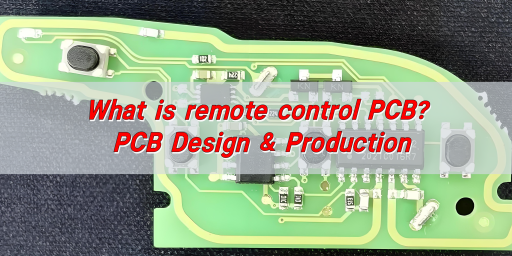
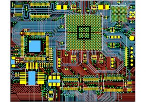
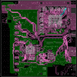
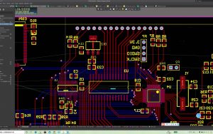
What is remote control PCB? The remote control PCB is an electronic circuit board inside the remote control, which is used to connect and support various electronic components to realize signal transmission and processing. It connects the microcontroller, communication module, input components, and power management components through conductive lines, so that the remote control can receive the user’s input signal, convert it into a control signal, and realize remote control of equipment such as TVs and air conditioners.
What is remote control PCB?
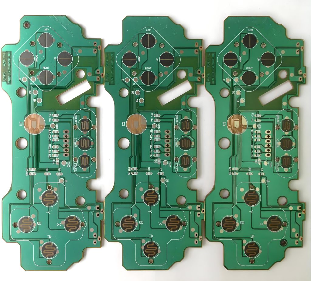
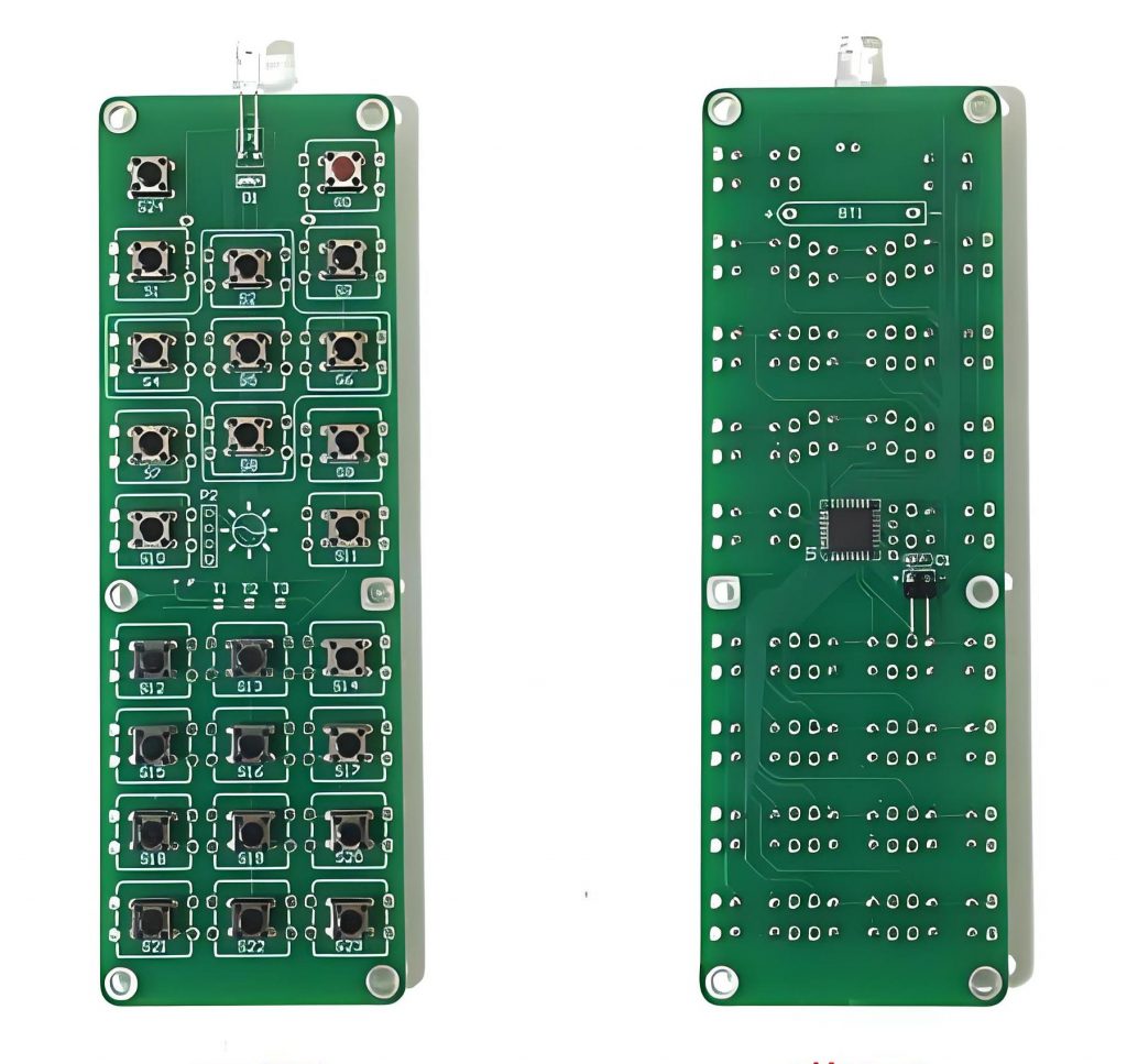
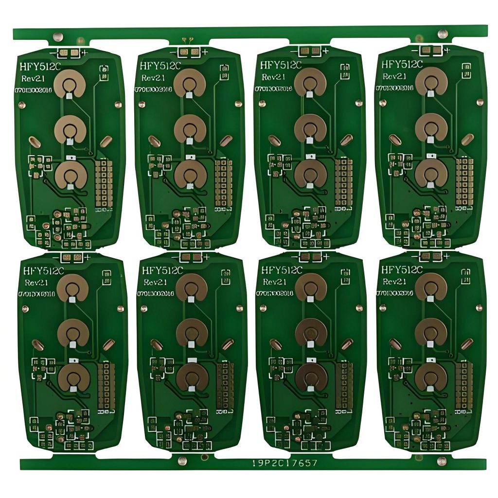
The remote control PCB refers to the printed circuit board used in the remote control. It is the core component inside the remote control, responsible for connecting various electronic components to realize various functions of the remote control.
The remote control PCB is usually composed of multiple layers of conductive metal (usually copper foil) and insulating materials. These metal layers are designed into a complex circuit network, and the combination of wiring and insulating materials enables electronic components to achieve electrical connection and functional integration.
The electronic components on the PCB include resistors, capacitors, transistors, integrated circuits (ICs), etc. They are connected together through the metal network on the PCB to form a complete circuit, thereby realizing various functions of the remote control.
The types of remote control PCB mainly include single-sided board, double-sided board and multi-layer board:
- Single-sided board: the most basic PCB type, suitable for simple circuit design.
- Double-sided board: wiring on both sides, suitable for more complex circuit design.
- Multi-layer board: can be further divided into middle and bottom boards and high-layer boards, mainly used for high-end equipment.
Remote control PCB is widely used in various electronic devices. Through the design and layout of PCB, the reception, processing and output of remote control signals can be realized, so as to control the switch, volume adjustment, channel selection and other functions of related equipment.
How to design remote control PCB?
Designing remote control PCB requires comprehensive consideration of functional requirements, component selection, circuit design, layout and wiring, power management, signal integrity, electromagnetic compatibility and thermal design.
1. Functional requirements analysis
- Determine the control function: clarify which devices and functions the remote control needs to control, such as switch, volume adjustment, channel switching, etc.
- Signal transmission method: Select a suitable signal transmission method, select the corresponding components and design layout according to the signal type.
2. Component selection
- Microcontroller (MCU): Select a suitable MCU, and select an MCU with sufficient processing power and input/output interface according to functional requirements.
- Communication module: Select the corresponding communication module according to the signal type, such as infrared transmission module, radio frequency module or Bluetooth module.
- Input component: Select a suitable button, touch screen or other input component for user operation and control.
- Power management component: Select a suitable power management component, such as battery management chip, voltage regulator, etc., to ensure a stable power supply.
- Draw a circuit schematic: Use circuit design software (such as Altium Designer, Eagle, etc.) to draw a circuit schematic and connect all components according to functional requirements.
- Check the circuit: Carefully check the circuit schematic to ensure that all connections are correct, there are no short circuits or open circuits, etc., and perform circuit analysis and simulation to verify the feasibility of the circuit.
4. PCB layout and wiring
- Layout: PCB layout should be carried out according to the schematic diagram, and the position of components should be arranged reasonably to minimize signal interference and noise. High-frequency components and sensitive components should be kept away from power lines and ground lines.
- Wiring: When wiring PCB, try to use short and straight lines to avoid long lines and too many corners. Pay attention to the layout of signal lines and ground lines to ensure stable signal transmission.
- Impedance matching: For high-frequency signal lines, impedance matching design should be carried out to reduce signal reflection and interference and improve the reliability of signal transmission.
5. Power supply design
- Power supply circuit: Design a reasonable power supply circuit, including power input, filtering, voltage regulation and other parts to ensure stable power supply and avoid the influence of power supply noise on the circuit.
- Power management: Design a power management strategy according to the power consumption requirements of the remote control to extend battery life.
6. Signal integrity and electromagnetic compatibility
- Signal integrity: For high-speed and high-frequency signals, perform signal integrity analysis and design, optimize signal transmission paths, reduce signal distortion and reflection, and ensure signal integrity.
- Electromagnetic compatibility (EMC): Take measures to improve the electromagnetic compatibility of PCB, reduce electromagnetic interference and radiation, and meet relevant EMC standards.
7. Thermal design
- Heat dissipation design: According to the power consumption and heat dissipation requirements of the components, perform heat dissipation design, reasonably arrange heat dissipation components, and ensure that the components are within the normal operating temperature range.
- Thermal management: Use thermal management strategies to improve the heat dissipation performance of PCB.
8. Testing and verification
- Functional test: Perform functional test on remote control PCB to ensure that all functions work properly, including signal transmission, input response, etc.
- Performance test: Perform performance test to ensure that the performance of PCB meets the design requirements.
- Reliability test: Perform reliability test, such as vibration test, temperature cycle test, etc., to ensure the reliability and stability of PCB in various environments.
What does the remote control PCB consist of?
The main components of remote control PCB include mainboard, remote control chip, battery interface, button, indicator light and shell. Among them, the motherboard is the core part of the entire circuit board, and the remote control chip is an important part of controlling the remote control.
- Motherboard: The core part of the circuit board, carrying other electronic components.
- Remote control chip: Process key signals, encoding signals and control other circuit components.
- Battery interface: Provide power support for other components on the circuit board.
- Key module: Receive user operation instructions and convert the instructions into electrical signals.
- Indicator light: Display the status or function of the remote control.
- Shell: Protect internal components and provide users with a grip.
How does a remote control PCB work?
The working principle of the remote control PCB mainly involves signal generation, transmission and reception.
1. User input
- Button or touch screen operation: The user selects the function or command to be controlled by pressing a button or touching the screen. These input devices convert the user’s operation into electrical signals and send them to the microcontroller (MCU).
2. Signal processing
- Microcontroller processing: After receiving the input signal, the microcontroller processes and encodes the signal according to the preset program logic.
- Coding: Control signals are usually encoded into a specific format for easy transmission and identification. The encoded signal contains complete information required for device control.
3. Signal transmission
- Infrared transmission: For infrared remote control, MCU sends the encoded signal to the infrared transmitting module, which converts the electrical signal into an infrared light signal and transmits it through the infrared transmitting diode.
- RF transmission: For RF remote control, MCU sends the encoded signal to the RF module, which modulates the signal to a specific frequency and transmits it. RF signals have stronger penetration and longer transmission distance.
- Bluetooth transmission: For Bluetooth remote control, MCU transmits the signal to the receiving device wirelessly through the Bluetooth module, which is responsible for signal modulation, encoding and transmission.
4. Signal reception
- Receiving device: The receiving device (such as TV, air conditioner, etc.) is equipped with a corresponding receiving module to receive the signal sent by the remote control.
- Decoding and execution: After receiving the signal, the receiving module decodes it, converts it into a control instruction, and then performs the corresponding operation according to the instruction.
Through the above steps, the remote control PCB realizes the complete process from user input to device control, enabling users to conveniently operate various devices remotely.
How to produce remote control PCB?
The production process of remote control PCB mainly includes the following steps:
- Design stage: The design stage includes determining the function of the circuit, laying out components, drawing wire paths, etc.
- Raw material preparation: According to the design requirements, purchase suitable substrate materials, such as FR-4, which has good insulation, mechanical strength and cost-effectiveness, and is suitable for most common electronic products.
- Cutting and drilling: Cut the copper clad board into the required size, and use a high-precision drilling machine to drill precise through holes on the circuit board. These holes will be used for electrical connections between different layers.
- Copper deposition: The hole wall of the PCB is bulked to enhance adhesion, and then a copper foil layer is deposited on the hole wall by electrochemical method to ensure the conductivity of the hole.
- Line exposure: Use LDI technology to accurately project the circuit diagram onto the copper clad layer of the PCB, and form the prototype of the circuit diagram through exposure and development of the photosensitive dry film.
- Electroplating: Further increase the thickness of the copper layer on the developed circuit and hole wall to ensure its conductivity and mechanical strength.
- Outer layer etching: Etch the outer layer of the PCB to form the required circuits and pads.
- Gold treatment: Perform gold treatment on the exposed key PAD position to protect the copper layer and prevent oxidation.
- Shape treatment: Perform shape treatment on the PCB substrate and finally complete the production.
What should we pay attention to during the production of remote control PCB?
In the production process of remote control PCB, the following key aspects need to be paid attention to to ensure product quality and performance:
1. Design stage
- Design review: Ensure that the circuit design is correct and meets the functional and manufacturing requirements.
- Follow standards: Strictly follow industry standards and specifications, such as IPC standards, to ensure the manufacturability of the design.
2. Material selection
- High-quality materials: Select substrate materials and copper foil that meet the specifications to ensure good insulation and conductivity.
- Supplier management: Select suppliers with good reputation to ensure stable and reliable material quality.
3. Manufacturing process
- Process control: Strictly control key process parameters such as exposure, etching, and lamination to ensure the stability and consistency of the production process.
- Standard Standardized operation: formulate detailed operating procedures to ensure that operators operate according to unified standards and reduce human errors.
4. Quality inspection
- Intermediate inspection: set up multiple inspection points during the production process to find and correct problems in time.
- Finished product inspection: conduct comprehensive finished product inspection, including functional testing, electrical performance testing and appearance inspection, to ensure that the product meets quality standards.
- Thermal management: rationally layout heat dissipation components and heat dissipation channels to ensure that the components are within the normal operating temperature range.
- Electromagnetic compatibility: take measures to improve the electromagnetic compatibility of PCB and reduce electromagnetic interference and radiation.
Through the above measures, the production quality of remote control PCB can be effectively improved to ensure its reliability and performance in practical applications.
How to choose a suitable remote control PCB supplier?
Selecting a remote control PCB supplier can be considered from the following points:
1. Comprehensive strength
- Production capacity: pay attention to the production line, equipment and workers to ensure that the production scale and delivery period can be met, and understand the ability to respond to emergency orders.
- Technical level: check whether there are advanced process capabilities and R&D teams, and whether they can provide technical support.
- Quality control: examine whether there are quality certifications and complete testing processes and equipment.
2. Service quality
- Pre-sales service: see whether it can provide comprehensive technical consultation, respond to needs in a timely manner, and provide quotations and samples.
- After-sales service: understand the after-sales guarantee policy and team situation.
3. Reputation
- Customer evaluation: view other customer evaluations through various channels.
- Industry status: understand its popularity and cooperation in the industry.
4. Price cost
- Price comparison: compare multiple quotations, pay attention to price composition and long-term cooperation discounts.
- Cost-effectiveness evaluation: comprehensively consider quality, service, etc. to evaluate cost-effectiveness.
As a professional PCB manufacturer, BEST Technology has strong design and technical support capabilities, and can provide customized remote control PCB design solutions according to customer needs, and ensure reasonable layout and stable signals.
At the same time, we have advanced production equipment and flexible production scale, which can efficiently produce various types of remote control PCBs to meet the needs from small batch proofing to large batch production; in terms of quality control, we follow a strict quality management system and use advanced testing equipment for comprehensive testing to ensure that the quality of each PCB is reliable and defect-free.
In addition, we focus on on-time delivery, provide high-quality customer service and technical support, and respond quickly to customer needs to ensure that customers are worry-free during use and enjoy a good service experience.


