What Does CTR Stand for on a PCB? CTR, or Current Transfer Ratio, is a measure of efficiency in optocouplers, which are devices that transmit signals between isolated parts of a circuit. Optocouplers use light-emitting diodes (LEDs) and photodetectors to pass signals while maintaining electrical separation. This separation prevents issues like interference and surges from traveling through the circuit.
CTR is represented as a percentage, showing how much input current is successfully transferred to the output. For instance, if an optocouplerās LED consumes 10 mA of input current and the photodetector outputs 8 mA, the CTR is 80%. Higher CTR values indicate more efficient current transfer, a critical factor in maintaining signal integrity.
Optocouplers are widely used in applications like power supplies, microcontroller interfaces, and industrial automation. CTR ensures that these devices perform as expected, allowing signals to pass efficiently without compromising isolation.
How Is CTR Calculated and Measured?
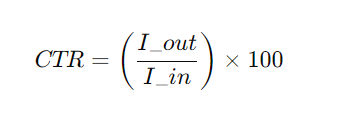
CTR, or Current Transfer Ratio, is calculated using the formula:
CTR (%) = (Output Current / Input Current) Ć 100
This straightforward calculation provides insight into how efficiently an optocoupler transfers current from its input (LED side) to its output (photodetector side). Letās understand this with a practical example.
Example: Calculating CTR for an Optocoupler
Imagine youāre using an optocoupler in a circuit where:
Input Current (I_in) = 10 mA (current supplied to the LED inside the optocoupler)
Output Current (I_out) = 7.5 mA (current delivered by the photodetector on the output side)
To calculate the CTR:
Substituting the values:

This result means the optocoupler transfers 75% of the input current to the output. The remaining 25% might be lost due to inefficiencies within the optocoupler, such as LED light output or photodetector sensitivity.
Using CTR to Select Components
In practice, engineers compare the calculated CTR to the componentās datasheet specifications. For instance:
- If the datasheet specifies a minimum CTR of 70% for your application, the measured value of 75% indicates the component performs adequately.
- If the CTR drops below the required threshold (e.g., 65%), the optocoupler might be unsuitable for the circuit or indicate a degraded component.
Factors That Influence CTR in Optocouplers
The main factors that affect the Current Transfer Ratio (CTR) of an optocoupler include the light source’s luminous intensity, ambient temperature, LED current (IF), collector-emitter voltage (VCE), and aging effects.
- Light Source’s Luminous Intensity
The luminous intensity of the light source depends on the forward current (IF) applied to it. The higher the forward current, the brighter the light, and the higher the CTR. However, operating at higher forward currents will reduce the lifetime of the optocoupler more quickly, so there needs to be a balance between CTR and lifetime when designing.
- Ambient Temperature
Ambient temperature significantly affects CTR. The luminous efficiency of the LED has a negative temperature coefficient, while the amplification factor of the phototransistor has a positive temperature coefficient. Therefore, in high-temperature environments, the CTR will decrease. For example, at 25Ā°C, the CTR may be 100%, but at 60Ā°C, it could drop to 60%.
- LED Current (IF)
The input current (IF) directly impacts the CTR. It is often necessary to carefully adjust IF to ensure the appropriate CTR. A larger IF will increase CTR, but both too high or too low a value of IF can affect the optocoupler’s performance.
- Collector-Emitter Voltage (VCE
The collector-emitter voltage (VCE) on the output side also has an impact on CTR. It is necessary to consider the effect of VCE on CTR during the design process to ensure the stability of the optocoupler under different operating conditions.
- Aging
Over time, the light output of the LED gradually diminishes, causing the CTR to decrease. The design should account for this reduction in CTR and allow for a margin to ensure stable operation over the long term.
The Role of CTR in PCB Design
Optocouplers play a vital role in circuits requiring electrical isolation. For instance, in industrial systems, sensitive control signals often need to be protected from high-voltage environments. Optocouplers achieve this while ensuring the signal reaches its destination.
Low CTR values can lead to insufficient output current, potentially causing the circuit to fail. On the other hand, choosing optocouplers with excessively high CTR can result in overengineering, increasing costs without significant benefits. Engineers must strike a balance by selecting components with CTR values tailored to the applicationās needs.
Why CTR Values Change Over Time?
No electronic component is immune to wear and tear, and optocouplers are no exception. Over time, factors like temperature fluctuations, environmental conditions, and extended usage can alter an optocouplerās CTR. While these changes are usually gradual, they can affect circuit performance if not accounted for during the design phase.
For instance, an optocoupler used in a high-temperature environment may experience accelerated degradation, causing its CTR to decline. To counter this, engineers often design circuits with a margin for error, ensuring the system remains operational even if the CTR drops slightly.
How to Select the Right CTR for Your PCB?
Selecting the right CTR requires understanding your circuitās requirements. Here are a few tips to guide the selection process:
- Know Your Current Needs: Determine the input and output current requirements for your circuit.
- Consider Environmental Conditions: If your device operates in extreme temperatures, choose optocouplers rated for those conditions.
- Plan for Aging: Account for potential decreases in CTR over time by adding a safety margin.
- Working with reliable suppliers who provide detailed component specifications makes it easier to find optocouplers that meet your needs.
CTR, or Current Transfer Ratio, is more than just an abbreviation on a PCB. It represents the efficiency of signal transfer in optocouplers, ensuring that circuits operate reliably while maintaining electrical isolation. Understanding CTR is essential for designing efficient and durable electronic systems.
When designing or manufacturing PCBs, choosing the right components with suitable CTR values can make a significant difference. Reliable suppliers who understand the nuances of electronic design can help you achieve optimal results. Partner with us for high-quality PCBs that meet your specific needs, backed by expertise and precision.


