PCB Full Form
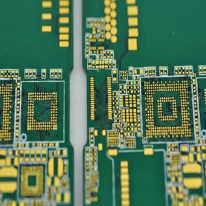
PCB stands for Printed Circuit Board. It is a crucial part of nearly all modern electronic devices. It acts as a physical base for electronic components while also providing the pathways to connect them electrically. Without PCBs, electronic devices would rely on cumbersome wiring that is prone to failure. With PCBs, electronics are compact, efficient, and highly reliable.
What Is a PCB?
A PCB (Printed Circuit Board), also known as a printed wiring board, is one of the most essential components in the electronics industry. It is used in almost every electronic device, from small gadgets like digital watches and calculators to large systems such as computers, communication equipment, and military weaponry. Wherever electronic components like integrated circuits are present, PCBs are necessary to electrically connect them.
In the early stages, paper-based copper-clad PCBs were commonly used. However, with the introduction of semiconductor transistors in the 1950s, the demand for PCBs skyrocketed. The rapid development and widespread use of integrated circuits (ICs) further increased the need for smaller and more densely packed circuit boards. This has driven continuous advancements in PCB technology.
What Is a PCB Made Of?
PCBs consist of multiple layers, each serving a distinct purpose. Hereās a breakdown of the common layers:
1. Substrate
The substrate is the core material that provides mechanical strength to the PCB. The most common material is FR4, a fiberglass-reinforced epoxy resin. It provides mechanical support and offers good heat resistance. For flexible PCBs, materials like polyimide are used, allowing the board to bend without breaking.
ā2. Copper Layer
This is a thin sheet of copper laminated onto the substrate. It forms the conductive pathways that carry electrical signals. Depending on the PCBās design, there may be one or more copper layers. Single-layer boards have copper on one side, while multilayer boards have copper on multiple layers.
3. Solder Mask
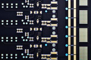
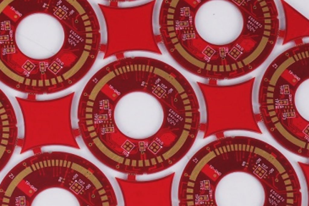
Solder mask is a layer of polymer coated on copper foil to protect unused copper tracks. It prevents oxidation and helps prevent solder bridges during assembly. It also adds an aesthetic touch to the PCB. It is usually green, hence the name “green oilā. While green is the most common color, solder masks can be blue, red, black, white or even transparent.
4. Silkscreen
Screen printing is a layer of paint, applied to a solder resistance film. The silkscreen layer contains printed information, such as component labels, polarity markings, and company logos. It helps technicians and engineers identify components and troubleshoot the board. The silkscreen is usually white but can be in other colors.
ā5. Through-holes and via holesā
Through holes are used to mount components and vias to connect the layers of the board together for electrical interconnection and thermal management.
ā6. Component
Electronic components, such as resistors, capacitors and integrated circuits (IC), mounted on the PCB, secured in place using soldering.
Types of PCB
PCB can be classified according to the number of circuit layers and hardness of the board.
1. According to the number of layers, a PCB can be divided into single sided PCB, double
sided PCB and multi-layer PCB. The common multi-layer board is generally 4-layer or 6-layer, and the complex multi-layer board can reach dozens of layers. PCB board has the following three main types of division:
- Single-sided PCB
This type has copper tracks on only one side of the board. It is the simplest and most cost-effective type of PCB. Single-sided PCBs are used in low-complexity devices like calculators, LED lighting, and simple power supplies.
- Double-Sided PCB
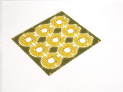
In double-sided PCBs, copper tracks are present on both sides of the board. They allow for more complex circuits compared to single-sided boards. They are commonly used in power supplies, audio systems, and industrial equipment.
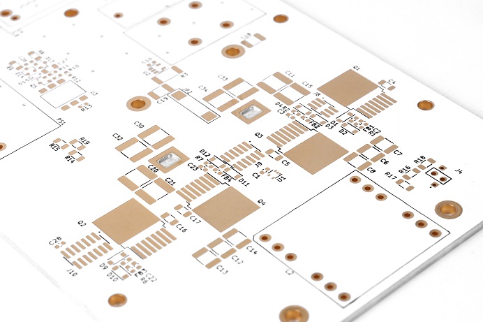
- Multilayer PCB
Multilayer PCBs consist of three or more layers of copper and insulating material stacked together. They are ideal for complex circuits requiring high density and performance. Applications include computers, smartphones, and aerospace systems.
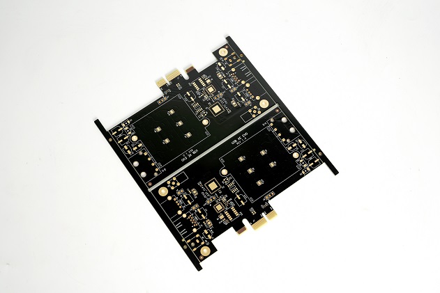
2. According to the hardness, a PCB can be divided into rigid PCB, flexible PCB and rigid-
flex PCB. Generally, the PCB shown in the left side below is rigid PCB, and the right side is flexible PCB (or short for FPC). The main difference between a rigid PCB and a flexible PCB is that a flexible PCB can be bent.
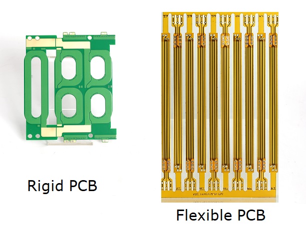
The common thickness of rigid PCB is 0.2mm, 0.4mm, 0.6mm, 0.8mm, 1.0mm, 1.2mm, 1.6mm, 2.0mm and so on. The common thickness of flexible PCB is 0.2mm. Since it has thinner thickness, the place where the parts are to be soldered will add a thick layer behind it (generally PI, FR4, stainless stiffeners), and the thickness of the thick layer is 0.2mm and 0.4mm. Common rigid PCB materials include: phenolic paper laminate, epoxy paper laminate, polyester glass felt laminate, epoxy glass cloth laminate. Flexible PCB materials commonly include: polyester film, polyimide (PI) film, fluorinated ethylene propylene film.
What Is the Difference Between PCB and PCBA?
Many people confuse PCB with PCBA, but they are not the same.
- A PCB is the bare board with copper traces and no components attached. It provides the framework for electronic connections.
- A PCBA (Printed Circuit Board Assembly) is a PCB with all components soldered and assembled onto it. It is a fully functional electronic circuit ready for integration into a device. In short, PCBA is the finished product, while PCB is the base.
In simple terms, a PCB is the blank canvas, while a PCBA is the finished painting.
What File Type Is Used for PCB?
When designing a PCB, specific file types are needed for manufacturing. The most commonly used file is the Gerber file. It contains all the information required to fabricate the PCB, including:
- Copper layer data: Specifies the layout of copper traces.
- Solder mask data: Indicates where the solder mask should be applied.
- Silkscreen data: Provides details for component labels and markings.
- Drill files: Indicate the size and location of holes.
Additional files used in PCB manufacturing include:
- Netlist files: Define the electrical connections between components.
- BOM (Bill of Materials): Lists all components required for assembly.
- Pick-and-Place files: Provide coordinates for placing components during assembly.
How Do You Know if Your PCB Is Damaged?
Detecting a damaged PCB early can prevent device failure. Here are some common signs of a damaged PCB.
- Physical Damage: Cracks, burns, or broken traces are visible on the board.
- Overheating: Discoloration or burnt areas indicate overheating issues.
- No Power: The device fails to power on, which could point to a short circuit or broken trace.
- Malfunctioning Components: Components behave erratically or fail to function.
- Unusual Odor: A burning smell may indicate a serious short circuit.
How to Fix a PCB Board?
Repairing a PCB depends on the nature and extent of the damage. Here are some common repair techniques:
1. Visual Inspection
Examine the PCB for visible damage, such as cracks, broken traces, or burnt components. Use a magnifying glass for a closer look.
2. Soldering Repairs
Resolder loose or broken connections using a soldering iron. Ensure the solder joints are clean and secure.
3. Trace Repair
For broken traces, use a conductive pen or solder a thin copper wire to bridge the gap.
4. Component Replacement
Identify and replace faulty components like resistors, capacitors, or ICs. Ensure the replacement components match the original specifications.
5. Testing
After repairs, use a multimeter to check for continuity and verify that the circuit functions correctly.
In some cases, especially with extensive damage, it may be more practical to replace the PCB rather than repair it.
Where Is PCB Used?
PCBs are used in nearly every industry, powering devices and systems that drive modern life. Some common applications include:
1. Consumer electronics – smartphones, tablets, laptops, televisions, and gaming consoles.
2. Automotive – engine control units, infotainment systems, sensors, and lighting.
3. Medical devices – diagnostic equipment, monitoring systems, pacemakers, and imaging devices like MRI machines.
4. Aerospace – navigation systems, communication devices, and flight control systems.
5. Industrial equipment – automation systems, machinery control, power supplies, and sensors used in industrial environments.
FAQs about PCB
1. Why Is a PCB Important in Electronics?
PCBs offer a reliable and efficient way to connect electronic components, enabling compact and functional devices.
2. Can a PCB Be Recycled?
Yes, PCBs can be recycled to recover valuable metals like copper, gold, and silver, reducing electronic waste.
3. How Long Does a PCB Last?
The lifespan of a PCB is around 50-70years, but it depends on its quality and usage conditions. High-quality PCBs can last for decades with proper care.
4. What Are Common PCB Defects?
Common defects include open circuits, short circuits, and misaligned layers, which can affect performance.
5. How Do You Test a PCB?
Testing methods include Automated Optical Inspection (AOI), In-Circuit Testing (ICT), and functional testing.
Choosing a reliable PCB manufacturer ensures you receive high-quality boards tailored to your needs. A trusted supplier like Best Technology can provide durable, efficient, and custom-designed PCBs that meet your project requirements, ensuring long-term success.


